Abstract: This application note describes how our T3 / E3 line interface unit (LIU) connects to Agere Ultramapper â„¢ in pure channel, transMUX, and map / demap applications.
Overview This application note describes how to connect Dallas DS3150 or DS315x series T3 / E3 LIU to Agere Ultramapper â„¢ devices. DS3150 or DS315x series T3 / E3 LIU can realize all functions of interface with T3 and E3 line physical layer. DS3150 contains only hardware and is a single-port T3 / E3 LIU, while DS3151, DS3152, DS3153 and DS3154 provide hardware, respectively CPU bus mode is provided on ports 1, 2, 3, or 4. As can be seen from the examples given in this application note, the DS3150 connection is the same as the DS315x series.
Agere Ultramapper devices include: Ultramapper, UltramapperLite, Ultramapper complete transmission and Ultraframer. The content discussed in this application note is only suitable for Agere's UltramapperLite and Ultraframer.
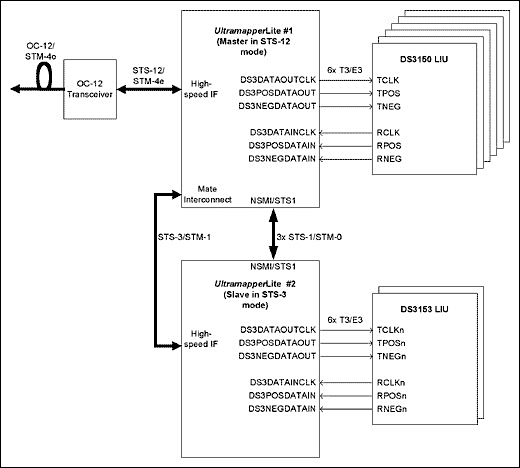
The figure below illustrates the use of the Dallas T3 / E3 LIU from the DS315x series or the multi-chip DS3150. The designer needs to decide which Dallas LIU to choose, depending on the line card / system being designed. Application of T3 / E3 pure channel application In this application note, two UltramapperLite are configured, terminating / transmitting 12 T3 / E3 signals, and mapping from / to T3 / E3 to STS-12 / STM-4 signals.

Figure 1. T3 / E3 pure channel application
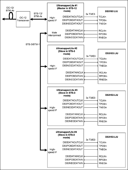
T3 / E3 TransMUX application In this application note, four UltramapperLite are configured to achieve two different occasions: one channel VT1.5 / VC11 is mapped between STS-12 and 12 channels T1 channelized into T3 signals, and one channel VT2 / VC12 is mapped It is the transMUX function between STS-12 and 12-channel E1 channelized into E3 signal.

Figure 2. T3 / E3 TransMUX application
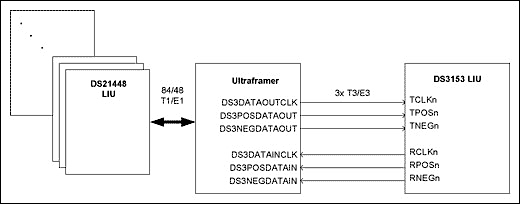
Application of Map / Demap for T3 / E3 and T1 / E1 In this application note, the Ultraframer is configured to implement map / demap between three channelized T3 / E3 signals and 84/48 T1 / E1 signals.

Figure 3. Map / Demap applications for T3 / E3 and T1 / E1
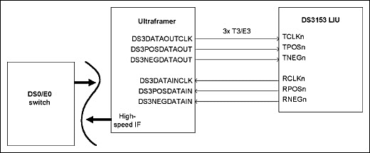
Map / Demap application for T3 / E3 and DS0 / E0 In this application note, the Ultraframer is configured to implement map / demap between three channelized T3 / E3 signals and up to 2016/1536 DS0 / E0 signal time slots .

Figure 4. T3 / E3 and DS0 / E0 Map / Demap application Dallas T3 / E3 line interface unit configuration Agere Ultramapper In M13 / E13 MUX / DeMUX applications, a 4.36MHZ T3 or 34.368MHz E3 should be provided on the DS3DATAOUTCLK pin Clock to realize M13 / E13 function. In SONET / SDH to T3 / E3 applications using DS3 / E3 digital jitter attenuators in the receiving channel: SONET / SDH ⇔ TMUX / STS-1LT ⇔ SPE ⇔ (DS3 / E3 digital jitter attenuator) ⇔ T3 / E3, not required DS3DATAOUT input can realize M13 / E13 function. But need to provide 44.736MHz DS3XCLK clock and 34.368 MHz E3XCLK clock, in order to achieve T3 / E3 digital jitter attenuation function. The Agere Ultramapper T3 / E3 line interface can be directly connected to DallasT3 / E3 LIU. Regarding the connection of T3 / E3, there is no difference between the host Ultramapper and the slave Ultramapper.
The connection between the T3 / E3 analog line and the line interface unit can be in bipolar mode or unipolar mode. Table 1 lists the register settings for Agere Ultramapper for D3 / E3 bipolar / unipolar control.
Table 1. Agere Ultramapper DS3 / E3 bipolar / unipolar control bits
Overview This application note describes how to connect Dallas DS3150 or DS315x series T3 / E3 LIU to Agere Ultramapper â„¢ devices. DS3150 or DS315x series T3 / E3 LIU can realize all functions of interface with T3 and E3 line physical layer. DS3150 contains only hardware and is a single-port T3 / E3 LIU, while DS3151, DS3152, DS3153 and DS3154 provide hardware, respectively CPU bus mode is provided on ports 1, 2, 3, or 4. As can be seen from the examples given in this application note, the DS3150 connection is the same as the DS315x series.
Agere Ultramapper devices include: Ultramapper, UltramapperLite, Ultramapper complete transmission and Ultraframer. The content discussed in this application note is only suitable for Agere's UltramapperLite and Ultraframer.
The figure below illustrates the use of the Dallas T3 / E3 LIU from the DS315x series or the multi-chip DS3150. The designer needs to decide which Dallas LIU to choose, depending on the line card / system being designed. Application of T3 / E3 pure channel application In this application note, two UltramapperLite are configured, terminating / transmitting 12 T3 / E3 signals, and mapping from / to T3 / E3 to STS-12 / STM-4 signals.

Figure 1. T3 / E3 pure channel application
T3 / E3 TransMUX application In this application note, four UltramapperLite are configured to achieve two different occasions: one channel VT1.5 / VC11 is mapped between STS-12 and 12 channels T1 channelized into T3 signals, and one channel VT2 / VC12 is mapped It is the transMUX function between STS-12 and 12-channel E1 channelized into E3 signal.

Figure 2. T3 / E3 TransMUX application
Application of Map / Demap for T3 / E3 and T1 / E1 In this application note, the Ultraframer is configured to implement map / demap between three channelized T3 / E3 signals and 84/48 T1 / E1 signals.

Figure 3. Map / Demap applications for T3 / E3 and T1 / E1
Map / Demap application for T3 / E3 and DS0 / E0 In this application note, the Ultraframer is configured to implement map / demap between three channelized T3 / E3 signals and up to 2016/1536 DS0 / E0 signal time slots .

Figure 4. T3 / E3 and DS0 / E0 Map / Demap application Dallas T3 / E3 line interface unit configuration Agere Ultramapper In M13 / E13 MUX / DeMUX applications, a 4.36MHZ T3 or 34.368MHz E3 should be provided on the DS3DATAOUTCLK pin Clock to realize M13 / E13 function. In SONET / SDH to T3 / E3 applications using DS3 / E3 digital jitter attenuators in the receiving channel: SONET / SDH ⇔ TMUX / STS-1LT ⇔ SPE ⇔ (DS3 / E3 digital jitter attenuator) ⇔ T3 / E3, not required DS3DATAOUT input can realize M13 / E13 function. But need to provide 44.736MHz DS3XCLK clock and 34.368 MHz E3XCLK clock, in order to achieve T3 / E3 digital jitter attenuation function. The Agere Ultramapper T3 / E3 line interface can be directly connected to DallasT3 / E3 LIU. Regarding the connection of T3 / E3, there is no difference between the host Ultramapper and the slave Ultramapper.
The connection between the T3 / E3 analog line and the line interface unit can be in bipolar mode or unipolar mode. Table 1 lists the register settings for Agere Ultramapper for D3 / E3 bipolar / unipolar control.
Table 1. Agere Ultramapper DS3 / E3 bipolar / unipolar control bits
| Block Name | Register Name | Address | DescripTIon |
| SPEMPR | SPEMPR_TDS3_BIPOLAR | 0x19 [1] | Transmit DS3 / E3 Bipolar / Unipolar. Note this is valid only if register 0x0018 [13:12] = 11. |
| SPEMPR | SPEMPR_RDS3_BIPOLAR | 0x19 [0] | Receive DS3 / E3 Bipolar / Unipolar. Note this is valid only if register 0x0018 [5: 4] = 11. |
| DS3DJA | DS3DJA_DS3_BIPOLAR | 0x15 [5: 0] | Per Channel Control Bit 1: HBD3 or B3ZS. 0: Unipolar. |
| DS3DJA | DS3DJA_DS3_B3ZS | 0x14 [5: 0] | Per Channel Control Bit 1: B3ZS coding. 0: HDB3 coding. |
| M13 | M13_BIPOLAR | 0x5D [0] | 1: B3ZS encoding / decoding, ie, DS3 I / O is in dual-rail mode where each rail carries a polarity of a bipolar I / O. 0: DS3 I / O is a single-rail, unencoded NRZ signal. |
| E13 | E13_TE3_BIPOLAR | 0x23 [2] | 1: E3 output is HDB3 encoded and dual-rail. 0: E3 output is single-rail unencoded. |
| E13 | E13_RE3_IN_CTL | 0x26 [5: 4] | 00: HDB3 decode disabled (input data on posiTIve rail only). 01: HDB3 decoder enabled, input on P / N rails. 10: HDB3 decoder disabled (input data on posiTIve rail only). 11: HDB3 decoder disabled, negaTIve input rail carries HDB3 error count from external LIU. |
Carbon Fiber Propeller, Folding Propeller For Drone, Multi Rotor Propeller
Carbon Fiber Propeller, Folding Propeller For Drone, Multi Rotor Propeller
shenzhen GC Electronics Co.,Ltd. , https://www.jmrdrone.com