Low-Power Bluetooth (BLE) is widely used in low-power wireless communication applications that need to acquire data and deliver them to a specified destination. In these applications, various types of sensors need to be powered by some form of energy to collect data and send it over BLE. It is generally not feasible to use a wired power supply to power these sensors. For example, sometimes some sensors are located on the human body. Battery-powered sensors are limited by battery life and require frequent charging. If an engineer really needs to design a BLE sensor application that does not need to be taken care of after installation, the system needs to utilize unused energy in the surrounding environment such as light, motion, pressure or heat.
This is where energy harvesting technology comes in. Energy harvesting is a new way to harvest energy from external sources and use it to power embedded devices. However, before we can reliably use BLE sensor nodes based on energy harvesting technology, we need to overcome some challenges, especially in low-power system design. This article will address some of the challenges and how to deal with them.
text:
Devices such as smartphones have brought many important changes to our daily lives. We use mobile phones to get information that directly affects our lives in real time, in relation to our health, the environment and even the way we shop. However, most of the information must be "pulled" out, either by connecting them to another device or by searching the network. These methods require the user to initiate an action when data is needed. But users sometimes don't even know what to look for or where to look for, for example, when they look for the price of a product in the store.
The solution is to have a system that can "push" messages to users in real time. Since smartphones are the best way to push information to users, the system should be able to send information to them quickly and easily. This is where Beacon comes in.
In wireless technology, Beacon is a system for broadcasting messages, so that nearby devices can receive these messages. Beacon makes it easy to transfer data to user devices without user intervention. Existing devices such as smartphones support a variety of methods that can be used to implement Beacon functionality. To ensure that Beacon is widely used, including support for mainstream devices, interoperability, low installation costs, and low power operation, BLE will be the best choice for Beacon communications.
Low-Power Bluetooth (BLE) is widely used in low-power wireless communication applications that need to transmit data over a small area. A wireless sensor node (WSN) is an example. The data is read from the sensor and is usually sent to a smartphone. The typical application flow in these sensor nodes is shown below:
These Beacons/sensors need to be powered by an energy source to ensure continuous operation and maintenance of the overall equipment size. It is generally not feasible to use these wireless power supplies to power these sensors, as these sensors are either on the human body or at the far end, so cable-powered designs do not work. Battery-powered sensors have problems such as limited battery life, frequent charging, and environmental damage during processing.
If we really want Beacon without any maintenance, we need to use unused energy in the surrounding environment such as light, motion, pressure or heat. This enables “no need to take care after installationâ€, enabling Beacon to be powered throughout its life cycle.
This is where energy harvesting technology comes in. Energy harvesting refers to the collection of unused energy from the surrounding environment and storage. The stored energy is used to power the WSN device, collect sensor data, and transmit data over BLE.
For EHS-powered devices, the energy consumed in the active state should not exceed the available energy in the EHS. Figure 4 shows an EHS-powered system that consumes more energy than EHS can provide. The output voltage of the EHS gradually drops until the output is completely stopped.
1) CPU clock frequency:
The system clock frequency determines the processing speed of the routine and the energy consumed during the period. The faster the clock, the faster the processing, but the higher the current consumption. In addition, each device has minimum and maximum clock frequency requirements and cannot exceed this requirement.
For EHS-based designs, an optimized clock frequency can be selected based on two factors:
a) Average current consumption
b) Peak current consumption
The capacity of the EHS must take into account these two factors. The average current is the average time current required in the active state, while the peak current is the instantaneous maximum current requirement in the active state, usually higher than the average current. It is possible that the average current required is within the capacity of the EHS, but the peak current will cause the EHS to suddenly deplete energy, causing the voltage to drop below the cutoff voltage. Note that processing time is part of the average current consumption calculation.
The figure below shows the power-time graph of a routine at two different frequencies (the first is 48 MHz and the second is 12 MH).
2) Low-power device startup
Once the embedded device is powered, it will complete a launcher before it can execute the application code. A typical launcher includes:
a) Initialize the memory
b) Set the interrupt vector
c) Configure peripherals and general purpose registers
d) Initialize the external clock (if any).
Each of these four steps takes up CPU processing time to complete, and therefore consumes energy. The amount of energy consumed depends on the device used, the system clock frequency, the amount of memory/registers initialized, and the time it takes to set up the external clock. Therefore, the startup process consumes a lot of power and must be optimized to ensure that it does not consume too much EH output. The following factors should be considered when writing the startup code:
a) Initialize only those memory and register sections that will be used, and keep the rest of the defaults.
b) Most wireless systems require a high precision external clock. These external clocks, such as the external clock oscillator and the watch crystal oscillator, have a longer settling time after startup. We should not let the system wait for the clock to stabilize while it is active, but put it in a low-power state (sleep/deep sleep state) and wake it up only when it is ready to use it. We can use an internal timer to achieve this.
3) Low power system startup
Once the device begins executing application code, it is often necessary to boot individual peripherals in the system. These peripherals may be located in the device, such as an ADC, or they may be outside the device, such as a sensor. The startup time of a single peripheral may not be long, but the total processing time of all peripherals may be long enough to exhaust the energy stored in the EHS.
We should calculate the peripheral startup time at the specified CPU frequency and then determine if the energy budget required to start all peripherals as a whole is feasible (faster), or whether the startup process needs to be divided into multiple phases (slower).
4) Phased application processing
Devices will have different application routines that require their own CPU bandwidth. These routines may be to configure a peripheral, receive data from a sensor, perform calculations, manage events, or interrupt. We should ensure that the energy used for processing does not exceed the capacity of the EHS. If they are exceeded, they should be divided into smaller subroutines and managed in stages. This divides the load on the EHS into multiple manageable current pulses, allowing the EHS to charge between active CPU processes.
In addition, between stages, the system should be placed in a low-power mode and a counter or Watchdog timer should be used as the wake-up source as an interrupt. Since the system must remain in this mode for a long period of time, the current requirements during the period should be as low as possible.
5) Wireless transmission
After collecting the data, they must be transmitted via BLE. The transmission can be done via a BLE connection or BLE broadcast, but the Beacon that supports energy harvesting can only use BLE broadcasts because it takes a lot of energy to establish the connection before using a connection to transfer data.
In general, wireless operation, whether sending (Tx) or accepting (Rx), is the most energy-intensive operation in a wireless device. We should ensure that the BLE operation is a separate process that is combined with other processes only if the EH output provides sufficient peak current.
Cypress's Power Management IC (PMIC)-based energy harvesters provide a battery-free technology for sensors and networks. Their precise output power control and efficient energy harvesting make them ideal for small wireless and Beacon applications. They can be used independently as power supplies or in conjunction with other battery devices such as lithium batteries to extend the life of the device. An EH PMIC can start at a low voltage to suit the needs of the application. Some products, such as the MB39C831, have maximum power point tracking (MPPT) capabilities. MPPT allows the built-in DC/DC converter to control the output charging power by tracking the input power to maximize power output. PMICs such as the MB39C811 support dual acquisition inputs that can harvest energy from two different sources. Optimized PMICs such as the S6AE101A (solar or light energy EHD optimized) have very low startup and static power consumption, allowing the use of a small solar cell.
Another consideration for batteryless wireless Beacons is the choice of MCUs. MCUs that are integrated into programmable systems such as SoCs and support a variety of low-power modes are ideal for such applications. Cypress's Programmable System-on-Chip (PSoC) is tightly integrated with the wide range of peripherals available for docking sensors. In particular, PSoC 4 BLE, which includes multiple low-power peripherals and a BLE RF unit and BLE protocol stack, provides a true single-chip BLE sensor node. In addition, its support for ultra-low power modes allows the system to work seamlessly with small power supplies such as energy harvesters and button cells. It has been proven that these energy harvesters plus PSoC are the best design for batteryless BLE sensor node applications.
For more information on PSoC 4 BLE, please refer to the application note AN91267. You can also refer to the application note AN92584 for details on how to further optimize the power consumption of the BLE system. Click here to learn more about Cypress's PMIC solutions and their latest features.
appendix
A1: Oscilloscope screenshot of each process in the EH powered BLE sensor node
1) The output voltage of the EHS varies with CPU activity. The yellow signal is the output voltage of the EHS and the green signal is the current consumed by the embedded device. The green peak is the current consumption during CPU activity, and the flat signal is the current consumption when the device is in low power mode.
This is where energy harvesting technology comes in. Energy harvesting is a new way to harvest energy from external sources and use it to power embedded devices. However, before we can reliably use BLE sensor nodes based on energy harvesting technology, we need to overcome some challenges, especially in low-power system design. This article will address some of the challenges and how to deal with them.
text:
Devices such as smartphones have brought many important changes to our daily lives. We use mobile phones to get information that directly affects our lives in real time, in relation to our health, the environment and even the way we shop. However, most of the information must be "pulled" out, either by connecting them to another device or by searching the network. These methods require the user to initiate an action when data is needed. But users sometimes don't even know what to look for or where to look for, for example, when they look for the price of a product in the store.
The solution is to have a system that can "push" messages to users in real time. Since smartphones are the best way to push information to users, the system should be able to send information to them quickly and easily. This is where Beacon comes in.
In wireless technology, Beacon is a system for broadcasting messages, so that nearby devices can receive these messages. Beacon makes it easy to transfer data to user devices without user intervention. Existing devices such as smartphones support a variety of methods that can be used to implement Beacon functionality. To ensure that Beacon is widely used, including support for mainstream devices, interoperability, low installation costs, and low power operation, BLE will be the best choice for Beacon communications.
Low-Power Bluetooth (BLE) is widely used in low-power wireless communication applications that need to transmit data over a small area. A wireless sensor node (WSN) is an example. The data is read from the sensor and is usually sent to a smartphone. The typical application flow in these sensor nodes is shown below:
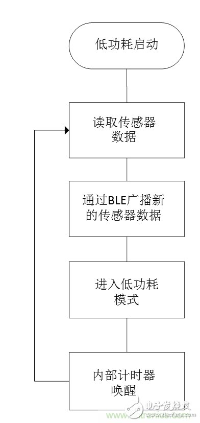
Figure 1 Typical process in a BLE sensor device
These Beacons/sensors need to be powered by an energy source to ensure continuous operation and maintenance of the overall equipment size. It is generally not feasible to use these wireless power supplies to power these sensors, as these sensors are either on the human body or at the far end, so cable-powered designs do not work. Battery-powered sensors have problems such as limited battery life, frequent charging, and environmental damage during processing.
If we really want Beacon without any maintenance, we need to use unused energy in the surrounding environment such as light, motion, pressure or heat. This enables “no need to take care after installationâ€, enabling Beacon to be powered throughout its life cycle.
This is where energy harvesting technology comes in. Energy harvesting refers to the collection of unused energy from the surrounding environment and storage. The stored energy is used to power the WSN device, collect sensor data, and transmit data over BLE.
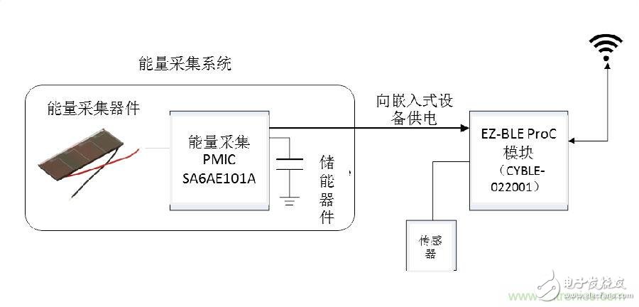
Figure 2 Block diagram of WSN equipment based on energy harvesting technology
The Energy Harvesting System (EHS) is a circuit that includes an energy harvesting device (EHD), an energy harvesting PMIC, and an energy storage device. The EH PMIC uses the energy provided by EHDs (such as solar cells, vibration sensors, and piezoelectric devices) to "turbulently" charge an energy storage device (usually a capacitor). The EHS then uses the stored charge to provide energy to another embedded device. The output power of the EHS changes as the state of the WSN changes. When the WSN is active, energy is consumed and the output voltage of the EHS begins to drop. When it is in a low power state, the output voltage of the EHS begins to rise as the energy storage device is charged. The figure below shows the process in which the output voltage of the EHS changes as the state of the embedded device changes. 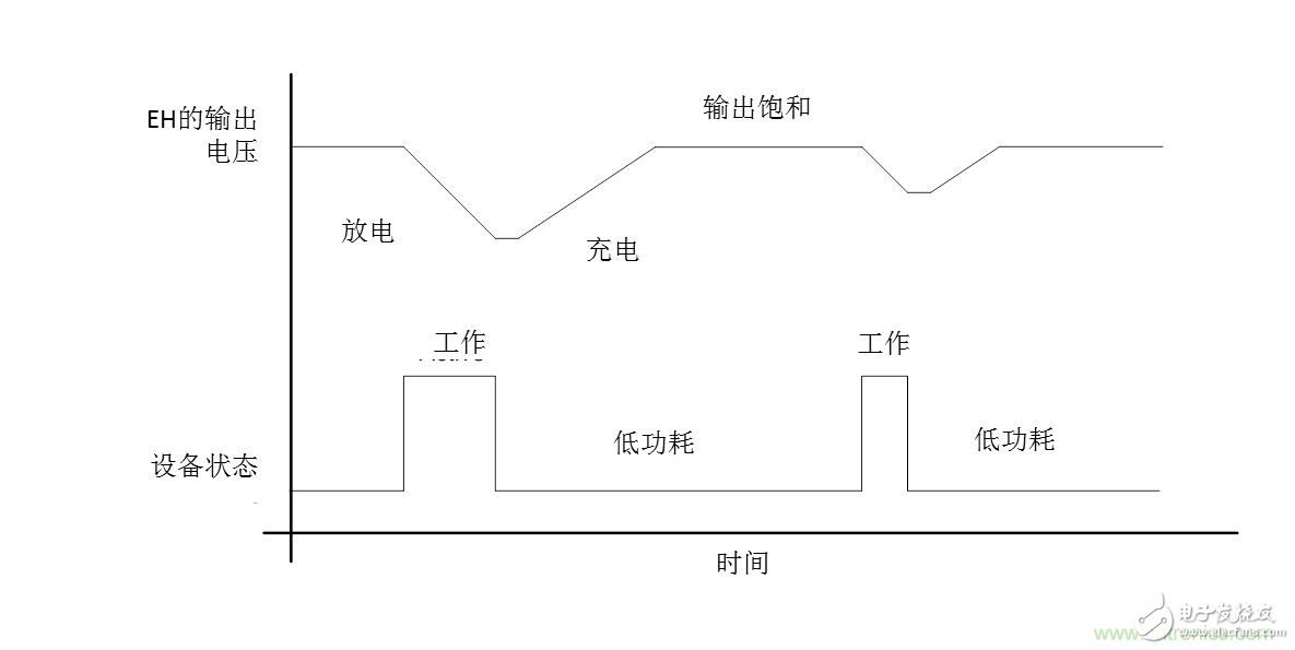
Figure 3 The output voltage of the EH changes as the state of the device changes.
For EHS-powered devices, the energy consumed in the active state should not exceed the available energy in the EHS. Figure 4 shows an EHS-powered system that consumes more energy than EHS can provide. The output voltage of the EHS gradually drops until the output is completely stopped.
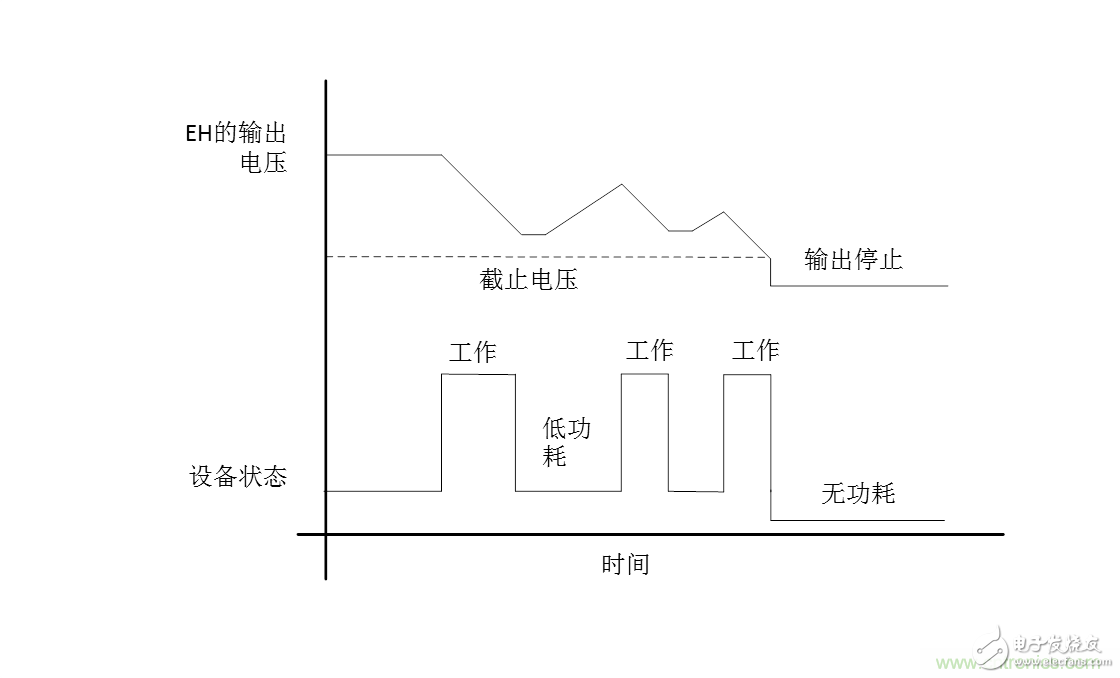
Figure 4 WSN shuts down due to insufficient power
This means that all aspects of the embedded system should be energy optimized so that it can operate seamlessly under EHS power. There are many subsystems in such systems, and they can be very power hungry and need to be optimized to ensure they do not pull down the EH's output voltage. Key areas of power optimization include: 1) CPU clock frequency:
The system clock frequency determines the processing speed of the routine and the energy consumed during the period. The faster the clock, the faster the processing, but the higher the current consumption. In addition, each device has minimum and maximum clock frequency requirements and cannot exceed this requirement.
For EHS-based designs, an optimized clock frequency can be selected based on two factors:
a) Average current consumption
b) Peak current consumption
The capacity of the EHS must take into account these two factors. The average current is the average time current required in the active state, while the peak current is the instantaneous maximum current requirement in the active state, usually higher than the average current. It is possible that the average current required is within the capacity of the EHS, but the peak current will cause the EHS to suddenly deplete energy, causing the voltage to drop below the cutoff voltage. Note that processing time is part of the average current consumption calculation.
The figure below shows the power-time graph of a routine at two different frequencies (the first is 48 MHz and the second is 12 MH).
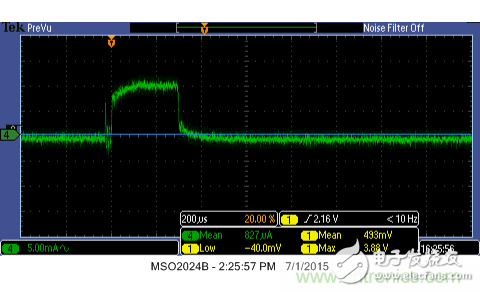
Figure 5 Current consumption of processing a routine at 48 MHz
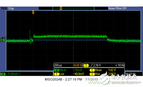
Figure 612 MHz to handle the current consumption of a routine
In this example, the routine that was processed at 48 MHz used a time of approximately 300 μs and consumed approximately 10 mA during this time. The routines processed at 12 MHz used a time of 1.1 ms and consumed only 4 mA during this time. This process has a higher average current consumption at 12 MHz but lower peak current requirements. Depending on the capacity of the EHS, we can use a shorter 48 MHz clock setting, or a longer 12 MHz clock setting, or a combination of both to allow the clock frequency to switch back and forth between different processes. We should consider this current distribution when choosing an optimized system frequency. 2) Low-power device startup
Once the embedded device is powered, it will complete a launcher before it can execute the application code. A typical launcher includes:
a) Initialize the memory
b) Set the interrupt vector
c) Configure peripherals and general purpose registers
d) Initialize the external clock (if any).
Each of these four steps takes up CPU processing time to complete, and therefore consumes energy. The amount of energy consumed depends on the device used, the system clock frequency, the amount of memory/registers initialized, and the time it takes to set up the external clock. Therefore, the startup process consumes a lot of power and must be optimized to ensure that it does not consume too much EH output. The following factors should be considered when writing the startup code:
a) Initialize only those memory and register sections that will be used, and keep the rest of the defaults.
b) Most wireless systems require a high precision external clock. These external clocks, such as the external clock oscillator and the watch crystal oscillator, have a longer settling time after startup. We should not let the system wait for the clock to stabilize while it is active, but put it in a low-power state (sleep/deep sleep state) and wake it up only when it is ready to use it. We can use an internal timer to achieve this.
3) Low power system startup
Once the device begins executing application code, it is often necessary to boot individual peripherals in the system. These peripherals may be located in the device, such as an ADC, or they may be outside the device, such as a sensor. The startup time of a single peripheral may not be long, but the total processing time of all peripherals may be long enough to exhaust the energy stored in the EHS.
We should calculate the peripheral startup time at the specified CPU frequency and then determine if the energy budget required to start all peripherals as a whole is feasible (faster), or whether the startup process needs to be divided into multiple phases (slower).
4) Phased application processing
Devices will have different application routines that require their own CPU bandwidth. These routines may be to configure a peripheral, receive data from a sensor, perform calculations, manage events, or interrupt. We should ensure that the energy used for processing does not exceed the capacity of the EHS. If they are exceeded, they should be divided into smaller subroutines and managed in stages. This divides the load on the EHS into multiple manageable current pulses, allowing the EHS to charge between active CPU processes.
In addition, between stages, the system should be placed in a low-power mode and a counter or Watchdog timer should be used as the wake-up source as an interrupt. Since the system must remain in this mode for a long period of time, the current requirements during the period should be as low as possible.
5) Wireless transmission
After collecting the data, they must be transmitted via BLE. The transmission can be done via a BLE connection or BLE broadcast, but the Beacon that supports energy harvesting can only use BLE broadcasts because it takes a lot of energy to establish the connection before using a connection to transfer data.
In general, wireless operation, whether sending (Tx) or accepting (Rx), is the most energy-intensive operation in a wireless device. We should ensure that the BLE operation is a separate process that is combined with other processes only if the EH output provides sufficient peak current.
Cypress's Power Management IC (PMIC)-based energy harvesters provide a battery-free technology for sensors and networks. Their precise output power control and efficient energy harvesting make them ideal for small wireless and Beacon applications. They can be used independently as power supplies or in conjunction with other battery devices such as lithium batteries to extend the life of the device. An EH PMIC can start at a low voltage to suit the needs of the application. Some products, such as the MB39C831, have maximum power point tracking (MPPT) capabilities. MPPT allows the built-in DC/DC converter to control the output charging power by tracking the input power to maximize power output. PMICs such as the MB39C811 support dual acquisition inputs that can harvest energy from two different sources. Optimized PMICs such as the S6AE101A (solar or light energy EHD optimized) have very low startup and static power consumption, allowing the use of a small solar cell.
Another consideration for batteryless wireless Beacons is the choice of MCUs. MCUs that are integrated into programmable systems such as SoCs and support a variety of low-power modes are ideal for such applications. Cypress's Programmable System-on-Chip (PSoC) is tightly integrated with the wide range of peripherals available for docking sensors. In particular, PSoC 4 BLE, which includes multiple low-power peripherals and a BLE RF unit and BLE protocol stack, provides a true single-chip BLE sensor node. In addition, its support for ultra-low power modes allows the system to work seamlessly with small power supplies such as energy harvesters and button cells. It has been proven that these energy harvesters plus PSoC are the best design for batteryless BLE sensor node applications.
For more information on PSoC 4 BLE, please refer to the application note AN91267. You can also refer to the application note AN92584 for details on how to further optimize the power consumption of the BLE system. Click here to learn more about Cypress's PMIC solutions and their latest features.
appendix
A1: Oscilloscope screenshot of each process in the EH powered BLE sensor node
1) The output voltage of the EHS varies with CPU activity. The yellow signal is the output voltage of the EHS and the green signal is the current consumed by the embedded device. The green peak is the current consumption during CPU activity, and the flat signal is the current consumption when the device is in low power mode.
Ei48 Transformer,Ei48 4Ohm Audio Transformer,48 Volt Transformer,Ei48 20W Audio Line Transformer,led transformer
Guang Er Zhong(Zhaoqing)Electronics Co., Ltd , https://www.gezadapter.com