Ultrasonic car parking anti-collision alarm is an important application of ultrasonic ranging. When the car is parked, the reflection of ultrasonic waves can be used to detect the distance between the rear of the car and the obstacle, providing a multi-level sound and light alarm. This article introduces a low-cost ultrasonic car parking anti-collision alarm design method using MC68HC705J1A single-chip as the core. The induction time of the alarm is less than 0.5s, and the ranging accuracy can reach 0.1m.
1 Principle of ultrasonic ranging
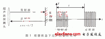
The principle of ultrasonic ranging is to record the time t from the transmitted signal to the first reflected signal according to the characteristic that the ultrasonic wave can be reflected back after encountering the obstacle, and use the formula s = c · t / 2 to calculate the distance s. Where c is the speed of sound, under standard conditions the speed of sound c = 331.4m / s. The principle of ultrasonic ranging is shown in Figure 1.

2 The composition of the ultrasonic car parking anti-collision alarm
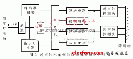
The composition of the ultrasonic car parking anti-collision alarm is shown in Figure 2.

The alarm is only used when the car is parked. The power of the reversing light + 12V is used. When reversing, the obstacle may be behind or on the side of the car. In order to ensure the accuracy of detecting obstacles in various situations, a dual-channel detection structure is adopted, and the shorter of the two channels is taken as the effective detection distance. The ultrasonic probe has two functions: electroacoustic conversion and acoustoelectric conversion. It is used to send and receive signals in time-sharing. The sound and light alarm circuit is directly controlled by the single-chip microcomputer, using different buzzer sounds and LED flashes of different colors to achieve multi-segment alarm.
3 The hardware circuit design of the ultrasonic car anti-collision anti-collision alarm
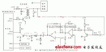
The hardware circuit principle of the ultrasonic car parking anti-collision alarm is shown in Figure 3 (only one detection circuit is given in the figure, and the other is the same).

MC68HC705J1A single chip microcomputer is one of Motorola's J series single chip microcomputers with the highest performance-price ratio. It is widely used in various small and medium-sized detection control systems. MC68HC705J1A is an 8-bit microcontroller with 1240 bytes EPROM / OTPROM. The main hardware resources are: 1240 bytes EPROM, 64 bytes RAM, 14 bidirectional input / output ports, multi-function counter, external interrupt, etc. Features such as watchdog and illegal address detection, and no minimum clock frequency selection. In the ultrasonic car reverse parking anti-collision alarm, make full use of the input and output functions of its bidirectional parallel port to perform signal transmission, reception and sound and light alarm control.
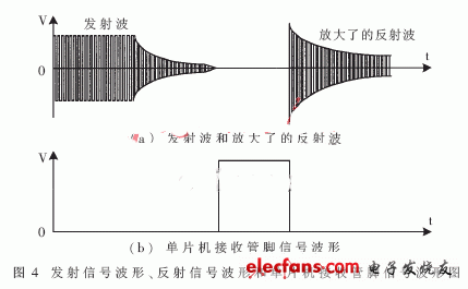
The frequency of the ultrasonic probe is 40kHz square wave. The software directly generates 20 square wave pulses on the sending pins PA6 and PA7 of the single-chip microcomputer, and then the transformer is boosted and transformed, and then emitted through the ultrasonic probe. Due to the recovery process of the sensor itself, there is still a damped oscillation not greater than 500 μs after the end of the launch. The transmitted signal is sent back to the receiving circuit at the same time.
The transmitted signal is reflected back after encountering an obstacle, received by the same ultrasonic probe and sent to the receiving circuit. The receiving circuit performs multi-stage amplification and detection of the reflected signal, and finally reaches the receiving pin PA0 or PA1 of the single-chip microcomputer through the switching circuit. When the receiving circuit has a signal, the switching transistor Q1 is turned on, PA0 or PA1 is low; otherwise, the transistor is turned off, PA0 or PA1 is high. By detecting the pin state of PA0 or PA1, the time when the ultrasonic probe receives the first reflected signal can be obtained, so as to calculate the time from sending the signal to receiving the first reflected signal, and then further calculate the obstacle and the car the distance. The transmitted signal waveform, the received circuit signal waveform and the single-chip receiver pin signal waveform are shown in Figure 4.

S-yuan Electronic Technology Limited , https://www.syuanelectronic.com