When it comes to reactive power, most people want to be as small as possible, and zero is best, so that more energy can be converted into active power without being wasted. As everyone knows, if there is no reactive power, there will be many power-consuming equipments that cannot work, because many electrical equipments rely on the establishment of alternating magnetic fields for energy conversion and transmission, and the electrical power needed to establish alternating magnetic fields and induced magnetic flux. It is called reactive power, so “reactive†is not “useless†electric power, but its power is not converted into mechanical energy and thermal energy; in addition to the active power supply, it also needs reactive power in the power supply system. Power supply, both are indispensable.
In the operation of the power grid, it is said that there is no work and no power, and the power factor is inevitable, because the power factor is the most powerful indicator to reflect the extent to which the apparent power of the power output is effectively utilized.

In the power triangle, the ratio of the active power P to the apparent power S is called the power factor, and the calculation formula is:
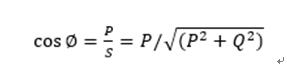
P is the active power and Q is the reactive power. It can be seen from the above equation that the power factor depends on the active power share.
Usually we want the power factor to be as large as possible, so that the reactive power in the circuit can be minimized, and the apparent power will be mostly used to supply the active power, thereby improving the efficiency of power transmission. If the power factor is low, the reactive power of the system for alternating magnetic field conversion is large. What are the main factors affecting the power factor? How can we achieve both effective use of apparent power and sufficient reactive power to ensure magnetic field conversion?
In the power system, in order to reduce the loss of the power supply transformer and the transmission line, improve the power supply efficiency and improve the power supply environment, the reactive power compensation method is generally adopted to provide sufficient reactive power for the system. Therefore, reactive power compensation plays a vital role in the power system. There are three main implementation methods: low-voltage individual compensation, low-voltage centralized compensation, and high-voltage centralized compensation. The following is a brief introduction to the scope of application and the advantages and disadvantages of using this type of compensation.

(1) Low-voltage individual compensation:
The low-voltage individual compensation is to separately connect one or more low-voltage capacitor banks to the electrical equipment according to the requirement of reactive power of individual electrical equipment, and it shares a set of circuit breakers with the electrical equipment. The control and protection device are switched at the same time as the motor. The random compensation is suitable for compensating the reactive power consumption of individual large-capacity and continuous operation (such as large and medium-sized asynchronous motors) to compensate for the excitation and reactive power. The advantage of low-voltage individual compensation is that when the power equipment is running, the reactive power compensation is input, and when the power equipment is out of service, the compensation equipment also exits, so no reactive power is returned. It has the advantages of less investment, small occupancy, easy installation, convenient and flexible configuration, simple maintenance and low accident rate.
(2) Low-pressure centralized compensation:
The low-voltage centralized compensation means that the low-voltage capacitor is connected to the low-voltage busbar side of the distribution transformer through the low-voltage switch, and the reactive power compensation switching device is used as the control protection device, and the switching of the capacitor is directly controlled according to the reactive load on the low-voltage bus. The switching of the capacitors is performed in the entire group, and smooth adjustment is not possible. The advantages of low-voltage compensation: simple wiring, small operation and maintenance workload, balance of reactive power, thereby improving the utilization ratio of distribution and distribution, reducing network loss, and having high economical efficiency. It is one of the commonly used means of reactive power compensation. .
(3) High-pressure centralized compensation:
High-voltage centralized compensation refers to the compensation method of installing the parallel capacitor bank directly on the 6~10kV high-voltage busbar of the substation. It is suitable for users to stay away from the substation or at the end of the power supply line. When the user has a certain high voltage load, it can reduce the reactive power consumption of the power system and can play a certain compensation role; the compensation device automatically casts according to the size of the load. Cut, so as to reasonably improve the user's power factor, to avoid the increase in power factor caused by the reduction of power factor. At the same time, it is easy to operate and maintain, and the compensation is high
In addition, there is a way to eliminate the need for any compensation equipment, to achieve effective use of apparent power from the natural power factor while ensuring the normal operation of the system. That is, various management or technical means are adopted to reduce the reactive power consumed by various electrical equipment, which is the most economical method for improving the power factor.
The above are several methods of reactive power compensation and their respective advantages and disadvantages, but how to evaluate the effect of reactive power compensation and the change of power factor before and after compensation? Obviously, if there is no comparison test before and after compensation, there will be no visual display of the compensation effect. A series of power detection equipment and power quality analysis equipment launched by Zhiyuan Electronics can solve this demand well, E6500 handheld power The mass analyzer can be used for power system power quality assessment, and it can record all power quality parameters such as harmonics, voltage, current, frequency, fluctuation, flicker, power and three-phase imbalance in the analysis site, with advanced power quality measurement. Function, and provide professional PC analysis software for secondary analysis, to provide users with the most accurate power fault diagnosis and analysis, determine the direction of rectification for power quality management, and comprehensively compare the power quality status before and after compensation.
Transformer Accessories,Innovative Chip Radiator,High Efficiency Chip Radiator,High Temperature Resistant Transformer Bushing
Tianhong Electric Power Technology Co., Ltd , https://www.tianhongtransformer.com