Keywords: wireless data transmission, automatic tuning resonance, MICRF102
1 Overview
MICRF102 is Micrel's newly launched long-range wireless data transmission chip. The chip uses the latest rapid wireless transmission technology of Micrel Company, which can realize the true "data input, wireless output" function. All of its tuning can be realized automatically in the IC, thus eliminating the trouble of manual tuning. The MICRF102 has a simple structure, is easy to use, and can be optimized to reduce costs. It is a low-cost and highly reliable wireless data transmission chip.It can be widely used in wireless keyboards, remote control access control systems, remote control fans, lighting switches, and wireless sensing. Data transmission and other fields.
MICRF102 adopts a new structure, which can tune all external antenna loops to the internal UHF synthesizer.
2 Main features and pin arrangement 
The main features of MICRF102 are as follows:
â— Integrate complete UHF in one chip;
◠The frequency range is 300MHz ~ 470MHz;
â— Data transmission rate up to 20kbps;
â— Automatic antenna tuning can be performed;
â— Only few peripheral components are needed;
◠Standby current is not more than 1μA.
MICRF102 adopts 8-pin SOIC package. Figure 1 is its pin arrangement diagram. The functional description of each pin is listed in Table 1.
Table 1 MICRF102 pin functions
| Pin number | Pin name | Function description |
| 1 | PC | Power control input. During normal operation, the voltage of this pin is limited to 0.3V ~ 0.6V |
| 2 | VDD | Positive supply voltage input |
| 3 | VSS | Ground terminal. The Power Supply bypass capacitor connected between VDD and VSS should be as close as possible to the two pins |
| 4 | REFOSC | Refer to oscillation input. A crystal oscillator can be connected between this pin and VSS, or a 0.5Vpp input clock coupled with AC can also be used |
| 5 | ASK | ASK (amplitude shift key) modulation data input terminal. Connect ASK to VDD for CW operation |
| 6 | ANTP | Drive the positive output of the antenna transmission |
| 7 | ANTM | Drive the negative output of the antenna |
| 8 | STBY | Transmit / standby control input. When this pin is pulled to VDD, the chip is in the transmitting state; when this pin is connected to VSS, the chip is in the standby state. |
3 Functional principle
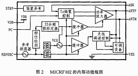
Figure 2 is the internal functional block diagram of MOCRF102, which mainly includes UHF synthesizer, buffer, antenna tuner, power amplifier, TX bias control, bias reference and adjustment circuit.
The role of UHF synthesizer is to generate carrier frequency with quadrature output,  The in-phase signal I is used to drive the power amplifier; the quadrature signal Q is used to compare with the phase of the antenna signal. The antenna tuner is used to detect the phase of the transmitted signal at the antenna end and control the tunable container of the antenna to achieve the purpose of tuning. The TX bias control unit is used to detect the antenna signal and control the bias current of the power amplifier. The adjustment circuit is used to provide the required bias for the internal circuit of the device.
A PCB (printed circuit board) antenna loop distribution network consisting of a resonator and a resistor is a UHF transmitter component required for remote operation (such as automatic keyless login). In addition, there is a differential variable vessel in MICRF102, which can be used to ensure that the transmission frequency and the reception frequency match when the overvoltage or temperature changes.
4 Application design
4.1 Selection of crystal oscillator
The external reference oscillator determines the transmission frequency, and the transmission frequency is 32 bits of the reference frequency, that is: fTx = 32fREFOSC. Choosing a reference oscillator plays a decisive role in the entire system. Therefore, it is necessary to select a crystal with an equivalent series resistance not greater than 20Ω. If a signal generator is used, its input amplitude should be selected between 200mVpp and 500mVpp.
4.2 Antenna design
MICRF102 has a special effect in driving the antenna loop. It has a double differential output that can drive inductive loads. The output stage includes a variable vessel that can automatically tune the inductance of the antenna to achieve the purpose of resonance. Accurately designing a high-Q antenna loop can set the center frequency of the resonant circuit more accurately. It should be noted that a small shift in the center frequency may reduce its transmit power. The antenna itself is an inductive element. A simple capacitor is connected in parallel with the antenna to form a resonant circuit, whose resonance frequency is determined by the following formula:
f = [1 / (4Ï€2CL)] 1/2
The tolerance of the inductor depends on the manufacturing method of the PCB. Generally, the resonance frequency of the antenna loop is adjusted by an adjustable capacitor, which can not only play a role in protecting the circuit, but also prevent parallel connection due to the inductor tolerance and the capacitor tolerance. The resulting frequency difference between transmitters, but at the same time will also increase costs and reduce system reliability. 
MICRF102 has a self-tuning function, which can be automatically tuned, so as to avoid the trouble of manual operation of the cloud, and can also dynamically adapt to its changes in impedance.
The output stage of MICRF102 is composed of 6.5pF adjustable capacitance, and its adjustable range is 5pF ~ 8pF. When MICRF102 detects the corresponding signal at the output of the power amplifier, it can automatically adjust the capacitance of the transformer until the antenna loop reaches resonance.
In the simplest design, the resonant frequency of the antenna loop should be based on a capacitance of 6.5pF. If satisfactory results cannot be achieved, a capacitor can be connected in series or in parallel at the antenna end.
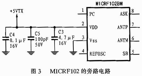
4.3 Bypass design
The correct bypass is to use a 100pF capacitor in parallel with an 4.7μF electrolytic capacitor. In addition, it is better to parallel a 0.1μF capacitor in the circuit. Figure 3 is the recommended bypass circuit.
4.4 Transmit power
The specific transmit power of MICRF102 itself has a load of 50Ω. The efficiency of the antenna determines the actual radiated power. A good antenna design can produce an output power of 67dBμV / m ~ 80dBμV / m within 3 meters. The PC pin can be used to set the required transmit power. The voltage on this pin is proportional to the differential voltage at the output of the power amplifier. When the PC pin voltage increases to 0.4V, the output power will be limited by the current and no longer change. Reducing the PC pin voltage can reduce the output power, and at the same time will also reduce the RF output power and its maximum range.
4.5 Output shutdown 
When the set power is too high or the power supply is temporarily turned off, the output of MICRF102 will be automatically turned off. This feature of the chip allows RF emissions to occur only when the synthesizer is in a fully controlled working state, thereby preventing the operator's unintentional emissions on unnecessary frequencies.
5 Application circuit
Figure 4 shows the typical application circuit of MICRF102. It can be seen that the peripheral components required for this circuit are only a few capacitors, resistors and antenna loops. Therefore, the design of MICRF102 is very simple and highly reliable. From wideband super regenerative transmitters to narrowband high-performance, superheterodyne receivers and other systems, MICRF102 is compatible with all of their ASK / OOK UHF receivers, with a frequency range of 300MHz to 47MHz, The data transmission rate can reach 20kpbs. If the MICRF102 transmitter is used in conjunction with the Micrel series antenna receiving chip MICRF001 / 002/022/003/004/007, the complete wireless data transmission receiving function can be realized, and the design and production costs can be greatly reduced.
This model can made wthin 12W to 24W.
Input: 100-240V~50/60Hz.
CE FCC ROHS Certificated.
Plug and Play, 12 Months warranty & Lifetime support.
Tip:(+)Center (-)Outer. Also can make (-)Center (+)Outer.
For the Led Strip/Wireless Router, ADSL Cats, HUB, Switches, Security Cameras, Audio/Video Power Supply.
We use a plastic bag and a white box to pack it. We put 100pcs or 200pcs even 250pcs into one carton.
24W Wall Charger,24W Wall Mount Charger,24W Wall Mount Charger,Home 24W Wall Charger
Shenzhen Waweis Technology Co., Ltd. , https://www.waweis.com