Recently, I was fortunate to participate in the judging of the TI 2011 Engibous Design Competition. The purpose of TI's move is to inspire college students to come up with the excellent work to participate in the Engibous Design Competition, and we are also looking for excellent analog and microcontroller/processor design. However, the real heroes that make this project possible are the students, professors, sponsors, consultants and departments. As a judge of the competition, I need to understand the stages of research, planning, design/simulation, manufacturing, prototype and testing.
I have reviewed 21 final reports. During the judging, I saw a lot of design projects and also learned about the implementation process of these projects. These designs detail the schematic, layout, and firmware code. Many designs use multidisciplinary knowledge such as histology, project feasibility studies, electronics, mechanics, firmware/software, and PC GUI.
In the end, the team at Rice University in Houston, Texas won the Engibous Design Competition. This team chose Mars as its next research area. The winning design team ("Electric Owl") developed a flight control electronic module for autonomous autonomous unmanned aerial vehicles, and the mission of the aircraft was to acquire its topographical data before humans boarded Mars. Their design considerations include the Martian atmosphere, energy harvesting, interstellar transportation, light propagation delays (communications), and high-radiation environmental issues.
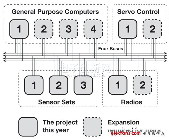
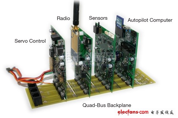
This is an ambitious plan, and the design team decided to first develop an aircraft with basic autopilot capabilities. Next, they implemented redundant sensor functionality to demonstrate the system's ability to accommodate redundancy, as shown in Figures 1 and 2.

Figure 1. System structure diagram of the Mars mission system.

Figure 2 shows the four boards that are plugged into the backplane.
When they tested the prototype, something really interesting happened. The design team simulated six actual flight tests during project implementation. For the first time, they verified that the servo board was able to properly receive, process, and send pulses of the correct timing. For the second test, the three-board test using the backplane (see Figure 2) ended prematurely. As a result, the design team discovered a telemetry technology vulnerability. After that, they simulated two flights to test the autopilot function, and finally conducted two tests to verify the effect of the redundant sensor.
In the end, the team designed and produced a complete set of avionics hardware for fixed-wing unmanned aerial vehicles. The device is modular in design and distributes system functions across four different boards. The design team wrote code for each board's firmware and tested it one by one, including basic autopilot algorithms and custom real-time kernels for general purpose computer boards.
After working hard for a year, it was very good! Using the analog chip, the design team showed us the basic functions of the system. This system has three times redundant sensor groups in the actual flight environment, and the avionics hardware is installed. In a standard RC body (spot, no special design required). The aircraft successfully processed the data from each set of sensors and used this data to keep the aircraft in a fixed course by autopilot.
Led Beads,Light Source Circuit Board,High Power Led Bead,Smd Led Beads
Shenzheng Weifu Circuit Technology Co.Ld , https://www.wfcircuit.com