Today, with "timely connection", most portable devices use the display as a selling point, and users can access and view video and Internet information through the display. Due to power consumption and viewing comfort, many devices are equipped with ambient light sensors—adding ambient light detection to the device. In dimly lit environments, the display backlight brightness can be adjusted to save battery power; in bright environments, enhanced font and backlight brightness can make the device display clearer and improve the user experience. This article discusses things to consider when designing products with ambient light sensors.
This article refers to the address: http://
Spectral sensitivity of light measurement
First, explore the visual response of the human eye to ambient light. The sensitivity of the human eye to light is usually expressed in terms of spectral light efficiency (also known as CIE curve) (Figure 1). As can be seen from the figure, the human eye does not see ultraviolet (< 400 nm) and infrared (> 700 nm) in the spectrum. In addition, the human eye is most sensitive to green light (~555 nm) and less sensitive to blue light and red light. To this end, we standardized the sensitivity curve to convert the incident optical power density (in μW/cm2) into the sensitivity unit of the human eye (in lux). At a wavelength of 555 nm, 1 lux corresponds to an optical power density of about 0.15 μW/cm 2 .
Figure 1. The photopic curve gives the human eye a visual response to different wavelengths of light. The human eye responds most strongly to green light, but does not see infrared (> 700 nm) or ultraviolet (< 400 nm) portions of the spectrum.
Manufacturing process and technical challenges make it difficult for low-cost ambient light sensors (ALS) to accurately reproduce the visual response of the human eye to light, and completely suppressing infrared and ultraviolet light is also a major problem. Since the spectrum of a common light source is very wide, even a slight deviation from the photopic curve, coupled with the inability to completely suppress infrared and ultraviolet light, can have a very large impact on the measurement accuracy of the ambient light sensor.
In fact, many commercial illuminometers do not accurately match the photopic curve. Therefore, most illuminance meters define a ?1' parameter that is used to indicate how well the illuminometer matches the optical CIE curve. Inexperienced users should also pay attention to another problem when operating commercial illuminance timers—many illuminance meters claim to be calibrated according to the National Institute of Standards and Technology (NIST) standards. In fact, this statement only indicates that the illuminometer is using incandescent (Class A) light sources provide accurate readings when tested, but do not guarantee measurement accuracy for non-incandescent sources, such as fluorescent lights, sunlight, or LEDs—and such sources are more common. In fact, due to the very low energy efficiency of incandescent light sources, countries are actively promoting the ban on the use of incandescent light sources in their daily lives.
Therefore, today's ambient light sensors do not fully match the optical CIE curve, but use the superposition principle to calculate the ambient light level. Most photosensors on the market today use two or more different types of photodiodes, each with different sensitivities to different regions of the spectrum. By arithmetically summing the outputs of these photodiodes and setting an appropriate adjustable gain for each photodiode, the sensor can more accurately measure the brightness of common ambient light sources.
For example, if two different types of photodiodes PD1 and PD2 give different readings for two different incident light sources, the gain constant for each photodiode can be obtained, allowing the sensor to provide accurate light under both sources. Strong measurement:
Light source 1 = gain 1 × PD1 + gain 2 × PD2
Light source 2 = gain 1 × PD1 + gain 2 × PD2
The more types of photodiodes, the greater the number of sources that can be precisely matched.
The spectral differences of common light sources in everyday life are very large (Figure 2). Taking the common light sources in homes and offices as an example, the spectral components of fluorescent and incandescent lamps are quite different—the infrared components of fluorescent lamps are extremely low, while the infrared components of incandescent lamps are much higher. Therefore, the data sheet for most ambient light sensors lists the response characteristics of these two common sources (Figure 3).
Figure 2. The above curves are a spectral comparison of sunlight (upper left), halogen/incandescent (upper right), fluorescent (lower left), and white LED (lower right).
Figure 3. The data for most ambient light sensors contains the correspondence between typical light sensitivity and illuminometer readings (lux). The figure above shows the response curve of the MAX44009 ambient light sensor.
Dynamic range of light measurement
The human eye is sensitive to a wide range of lighting conditions. In dark environments (which may take several minutes to accommodate this condition), the human eye is able to detect brightness levels as low as 10-4 lux. In the other extreme environment, even with a brightness of up to 108 lux, the human eye can perceive the darkness.
The typical ambient brightness that people find in everyday life is usually much narrower, from 0.1 lux outside at night to 300 lux in office lighting to 100,000 lux in sunlight. Most portable devices only need to accurately detect ambient light levels from 5 lux to about 1000 lux. In practical applications, the backlight effect of the display of the portable device is not completely consistent with the intensity of the sunlight. When the light intensity reaches a certain lower level, the display screen simply starts to maintain the minimum backlight brightness.
It is worth noting that the perception of brightness by the human eye is logarithmic (similar to the sensitivity of the human ear to sound). The light intensity increases almost 10 times, and the human eye can only perceive twice the brightness change. A similar transfer function can be used to represent the correspondence between the percent brightness of the display backlight and the relative ambient light intensity, as shown by the linear and logarithmic curves in Figure 4.
Figure 4a. This linear curve gives the correspondence between backlight intensity and relative light intensity. The black line is the ideal logarithmic curve, and the blue line is a fold line approximation, which is more suitable for implementation with the microcontroller code.
Figure 4b. These curves are the linear data in Figure 4a when the relative intensity is expressed in logarithmic coordinates. The black line is the ideal logarithmic curve, and the blue line is a fold line approximation, which is more suitable for implementation with the microcontroller code.
It can be seen that at lower levels of light intensity, a higher brightness measurement resolution is required; at higher levels of light intensity, a general resolution is sufficient. The easiest way to implement this mechanism is to use a high-resolution converter with front-end programmable gain to balance the wide dynamic range requirements under high light and high sensitivity requirements at low brightness.
Unlike other digital light sensors, the MAX44009 has an internal autoranging mechanism. This adjustment method enables the IC to automatically implement 22-bit dynamic range measurements without requiring the microcontroller to reconfigure registers, thereby increasing coding efficiency. In addition, the measurement results are compressed and represented in a 12-bit format, providing a pseudo logarithmic step size for the light measurement. Taking the MAX44009 as an example, the device uses a 4-bit exponent and an 8-bit mantissa to represent a 22-bit dynamic range. The resolution at low brightness can reach 0.045 lux/count, and the ambient light brightness has a higher count value.
Black glass effect
The look and feel of modern electronic devices, also known as their industrial design, are as important as the features and functions they provide. Users have seen modern portable devices as a symbol of "identity." For example, ambient light sensors are very important to the device, but the current popular practice is to hide these sensors so as not to affect the appearance and texture of the product.
For glass panels, a thin layer of black ink (absorbing almost all incident light) is usually applied to the sensor opening to "cover" it. A small amount of light passes through the ink and reaches the light sensor, enabling both ambient light measurements and a smooth, flat black border on the panel (Figure 5).
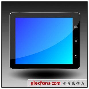
Figure 5. A typical tablet design with a black border panel around the LCD display. The user does not see the ambient light sensor hidden behind it.
Unfortunately, this layer of black ink greatly affects the normal operation of the light sensor, not only weakens the light reaching the sensor, but also changes the spectrum. First, discuss the issue of light attenuation. Most black inks only allow 2% to 10% of visible light to pass through, and 5 lux of external light source only 0.1 lux when it reaches the sensor! Therefore, the light sensor is required to have higher sensitivity. Second, although only 2% to 10% of visible light can penetrate the ink, almost all of the incident infrared radiation can penetrate the ink to reach the sensor, causing a change in the spectrum (Figure 6).
Figure 6. The above figure shows the typical spectral characteristics of black inks in current commercial electronic devices, showing the percentage of incident light transmission versus wavelength.
Uneven spectral transmissions make most photosensors recalibrated so that accurate ambient light measurement readings are obtained while placed under black ink, and factory settings that accurately measure ambient light without black glass conditions need to be re-adjusted. Because of this, the MAX44007 ambient light sensor provides multiple internal photodiodes. This flexibility allows the user to adjust for most applications and recalibrate the sensor response characteristics. The sensitivity of the MAX44007 is 0.025 lux/LSB.
Use of optical sensor interrupt pin
Most applications do not require real-time changes to the display backlight intensity, the purpose of which is to prevent spurs from responding to stray noise, such as swept shadows. In contrast, consistent changes in fast-responding ambient light enable users to use the device consistently without distracting to adjust display brightness to improve display. In addition, constantly polling the light sensor in the firmware (to check for changes in ambient light intensity) and noise suppression circuitry are also a burden on the application software resources. This increases the microcontroller processing load, which in turn slows down the response to user commands and increases power consumption.
Therefore, current optical sensors are equipped with a powerful function - the interrupt pin. The sensor continuously compares the ambient light measurement with the internal programmable window threshold and triggers an interrupt when the light intensity exceeds the threshold, reporting to the host controller that the lighting condition has changed substantially. A timer is usually used. When the timer expires, the interrupt is reported to the main controller to avoid noise and short-term fluctuations in the ambient light signal causing misoperation.
The interrupt pin makes the sensor application more intelligent and only makes a request to the primary controller when an operation is required. In this way, the resources of the main controller can be allocated to other tasks, or the microcontroller can be maintained in a low power wait state, thereby extending battery life. The typical application circuit (Figure 7) shows how to use the interrupt pin. It should be noted that the open-drain connection of this pin allows “wire-OR†to connect multiple devices and sources.
Figure 7. Typical application circuit for an ambient light sensor on a multipoint I2C bus showing how the interrupt pin is connected to the host controller.
to sum up
This article outlines the common problems in the design of light sensors for portable devices today. Identifying solutions early in development and working closely with IC vendors ensures system flexibility and reliability.
Jinhu Weibao Trading Co., Ltd , https://www.weibaoe-cigarette.com