The structure of the AC servo motor can be mainly divided into two parts, a stator part and a rotor part. The structure of the stator is basically the same as that of the stator of the rotary transformer, and two-phase windings with a mutual electrical angle of 90 degrees are also placed in the stator core. One group is a field winding and the other is a control winding. The AC servo motor is a two-phase AC motor. When the AC servo motor is used, a constant excitation voltage Uf is applied across the excitation winding, and a control voltage Uk is applied across the control winding. When the stator winding is applied with a voltage, the servo motor will quickly turn. The current flowing into the field winding and the control winding generates a rotating magnetic field in the motor. The steering of the rotating magnetic field determines the steering of the motor. When the voltage applied to any one of the windings is reversed, the direction of the rotating magnetic field changes. The direction has also changed.
The rotor inside the servo motor is a permanent magnet. The U/V/W three-phase electric motor controlled by the driver forms an electromagnetic field. The rotor rotates under the action of the magnetic field. At the same time, the encoder feedback signal from the motor is supplied to the driver. The driver according to the feedback value and target. The values ​​are compared to adjust the angle at which the rotor rotates. The accuracy of the servo motor is determined by the accuracy (number of lines) of the encoder.
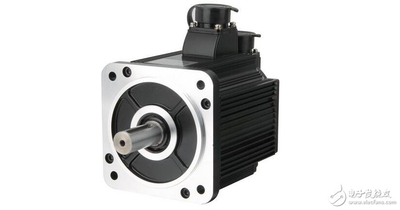
The configuration of the AC servo motor stator is basically similar to that of a capacitive split phase single phase asynchronous motor. The stator is provided with two windings with a position difference of 90°, one is the field winding Rf, which is always connected to the AC voltage Uf; the other is the control winding L, which is connected to the control signal voltage Uc. Therefore, the AC servo motor is also called two servo motors.
Frequency control of AC servo motor
As long as the power supply frequency f1 of the AC servo motor is changed, the motor speed can be changed. Therefore, the most application of the AC servo motor speed regulation is frequency conversion speed regulation.
The main link of the frequency conversion speed regulation is: the inverter that provides the variable frequency power supply for the AC motor.
Inverter points: AC-AC frequency conversion; AC-DC-AC frequency conversion.
(1) AC-AC frequency conversion
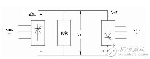
The thyristor rectifier directly converts the commercial frequency alternating current (frequency 50 Hz) into a pulsating alternating current with a lower frequency, the positive group outputs a positive pulse, the reverse group outputs a negative pulse, and the pulsating alternating current fundamental wave is a required variable frequency voltage.
The alternating current fluctuation obtained by the method is relatively large, and the maximum frequency is the frequency of the power frequency voltage input by the frequency converter.
(2) AC-DC-AC frequency conversion
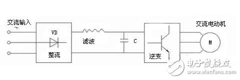
First, the alternating current is rectified into direct current, and then the direct current voltage is converted into a rectangular pulse wave voltage, and the fundamental wave of the rectangular pulse wave is the required variable frequency voltage.
The frequency fluctuation obtained by the frequency modulation method is small, the frequency modulation range is relatively wide, and the adjustment linearity is good.
In AC-DC-AC frequency conversion, according to whether the intermediate DC voltage is adjustable, it can be divided into intermediate DC voltage adjustable PWM inverter and intermediate DC voltage fixed PWM inverter; according to the intermediate DC circuit energy storage component is large capacitance or large inductance Divided into voltage type inverter and current type inverter.
SPWM (Sine Wave PWM) Inverter is the most widely used and most basic AC-DC-AC type inverter, which is widely used in AC speed control system.
SPWM transformer inverter modulation principle (taking single phase as an example)
Sinusoidal Pulse Width Modulation (SPWM) waveform: A series of equal-width unequal-width rectangular pulse waves equivalent to a sine wave.
Equivalent principle: The sine wave is divided into n equal parts, and the area of ​​each interval is replaced by a rectangular area of ​​equal width and unequal width. The positive and negative half cycles of the sine wave are treated as such.
SPWM control wave generation: sine wave - triangular wave modulation.
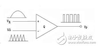
Q——voltage comparator;
UR - a sinusoidal control wave converted from a command pulse;
UΔ - triangular wave generator.
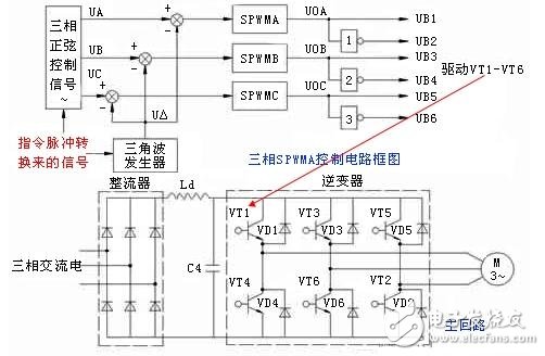
The rectifier converts the three-phase power frequency alternating current into direct current;
The inverter inverts the DC voltage into three-phase AC power to drive the motor to run.
AC servo motor SPWM frequency conversion speed regulation methodOne of the key components in the AC motor variable frequency speed control system is the inverter. Due to the requirements of speed regulation, the inverter must have the functions of continuously adjustable frequency, continuous adjustable output voltage, and a certain proportional relationship with frequency.
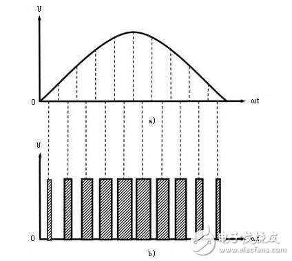
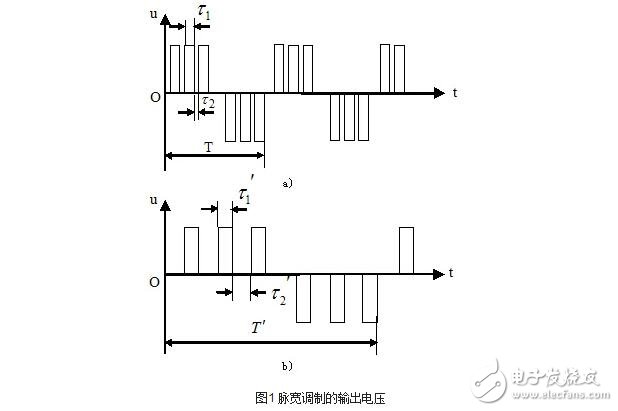
Variable frequency and variable voltage can be realized by using pulse width modulation inverter. As shown in the figure, since the average value of the voltage is proportional to the duty ratio, when the frequency is adjusted, the duty ratio of the output voltage pulse is changed, and the frequency conversion and the voltage transformation can be simultaneously realized. Compared with FIG. 1(a), the voltage period shown in FIG. 1(b) is increased (the frequency is lowered), and the duty ratio is decreased, so that the average voltage is lowered.
When the PWM method is used to control the on and off of the inverter tube, a set of rectangular pulses with the same amplitude and the same width can be obtained. The width of the rectangular pulse can be controlled to control the output voltage, and the modulation period can be controlled to control the output frequency. Pressure and frequency conversion. Since the output voltage waveform is a rectangular wave, it has many high-order harmonic components. For the motor, what is useful is the fundamental of the voltage. In order to reduce the influence of harmonics and improve the running performance of the motor, a symmetrical three-phase sine wave power supply should be used to supply the three-phase AC motor.
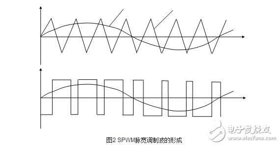
The output of a sinusoidal pulse width modulation inverter (SPWM) can obtain a set of rectangular pulse waveforms of equal width and not equal width to approximate an equivalent to a sinusoidal voltage wave. SPWM pulse width modulation waveform, as shown in Figure 2. When the sine value is the maximum value, the pulse width is also the largest, and the pulse interval is the smallest. Conversely, when the sine value is small, the pulse width is also small, and the pulse interval is large. Such a series of voltage pulses can greatly reduce the harmonic components in the load current.
A SPWM inverter with digital circuitry can be implemented in a software-based control mode. The advantage is less hardware, flexibility and intelligence. The disadvantage is that the pulse width of the SPWM needs to be determined by calculation, with a certain delay and response time. With the development of high-speed, high-precision multi-function microprocessors, microcontrollers and SPWM-specific chips, digital SPWM technology using microcomputer control has occupied the leading position of today's PWM inverters.
SPWM variable frequency speed control system, the function of each part:
Speed ​​reference: Given signal, control frequency, voltage and forward and reverse.
Smooth start loop: The start acceleration and deceleration time can be set with the mechanical load to achieve the purpose of soft start.
Function generator: keep the motor air gap flux constant when outputting low frequency signals, and compensate for the influence of stator voltage drop.
Voltage-frequency transformer: converts the voltage into frequency, generates a square wave through a frequency divider and a ring counter, and sends it into the modulation loop together with the triangular wave generated by the triangular wave generator.
Voltage regulator: Generates a sine wave with adjustable frequency and amplitude, sends it into the modulation loop, feeds it into the modulation loop, and performs SPWM conversion in the modulation loop to generate a three-phase pulse width modulation signal. In the base circuit, the signal is output to the base of the power transistor, that is, the main circuit of the SPWM is controlled to realize the frequency conversion speed regulation of the permanent magnet AC servo motor.
Current Detector: Overload protection.
POSH PLUS XL Disposable Pod Device
POSH PLUS XL Disposable Vape is a pre-filled Vape with 6 ML of salt nic e-liquid and comes packaged as a disposable unit. Allowing the user to enjoy a flavorful vape with zero up keep, and requiring a simple trip to the trash once the device has been used up. Each Disposable Device features an estimated 1500 puffs, and has a high capacity internal battery which is to be disposed of once the life cycle is complete. POSH PLUS XL Devices feature 6 ml of Salt Nicotine E-Liquid with the nicotine level of 45mg. Each Disposable features one (1) device per package and has a smooth mouth to lung draw which can be used with a draw to activate firing system. Huge bang for buck in a small package and available in 11 amazing flavors.
Features:
Disposable Device
4.5% nicotine
1500 puffs per device
6 ml Salt Nicotine
Disposable Posh Plus E-Cigarette Bar,Posh Flavors Plus E-Cigarette,Posh Puff E-Cigarette,Posh Puff Bar Ecig
Shenzhen Ousida Technology Co., Ltd , https://www.osdvape.com