At present, the feedforward power amplifier designed by Frees-cale's MRF9060 can achieve 30% efficiency. The Doherty amplifier, because it works in category C, can theoretically achieve an efficiency of 75%, so it is widely used in mobile communication front-end amplifiers. The Doherty power amplifier is used in the digital TV front-end system in combination with the predistortion technology, which makes the efficiency of the digital TV front-end power amplifier be further improved. Compared with the original feedforward, the actual working efficiency can be increased by at least 10%. The application in the front-end system will also be more and more extensive. This design mainly introduces the application of Doherty power amplifier in the front-end transmission system of digital TV to improve the efficiency of the front-end transmission system.
1 Doherty power amplifier principle overview
Doherty power amplifier is a kind of high-efficiency linear power amplifier specially for non-constant envelope modulation signal. It was first proposed by RF engineer WHDoherty of Bell Labs in the United States in 1936. The principle is shown in Figure 1.

The Doherty amplifier is mainly composed of two power amplifier units, a carrier amplifier and a peak amplifier. The signal enters from the input terminal of the amplifier, and is divided into two channels through a power divider and input into a carrier amplifier and a peak amplifier, respectively. After passing through the amplifier, the two signals are directly coupled out at the end. The most important feature of Doherty power amplifier is that it has two amplifier units with the same structure and different static operating point bias. The carrier amplifier is usually set as a class AB amplifier, and the peak amplifier is set as a class C amplifier. Another characteristic of the Doherty amplifier is that the carrier amplifier and peak amplifier have high requirements for the consistency of the structure and semiconductor characteristics.
The main power amplifier works in class B. When the input signal is relatively small, only the main power amplifier is in working state; when the output voltage of the tube reaches the peak saturation point, the theoretical efficiency can reach 78.5%. If the excitation is doubled at this time, the tube will be saturated when it reaches half of the peak, and the efficiency will also reach the maximum of 78.5%. At this time, the auxiliary power amplifier will also start to work with the main amplifier (Class C, the threshold is set to Half of the excitation signal voltage). The introduction of the auxiliary power amplifier reduces the load from the perspective of the main power amplifier, because the effect of the auxiliary power amplifier on the load is equivalent to a negative impedance connected in series. Small but continuously increasing (the current flowing through the load becomes larger). When the peak of the excitation is reached, the auxiliary power amplifier also reaches the maximum point of its own efficiency, so that the efficiency of the two power amplifiers combined is much higher than the efficiency of a single class B power amplifier. The maximum efficiency of a single Class B amplifier is 78.5% at the peak, and now the efficiency of 78.5% appears at half of the peak. So this system structure can achieve very high efficiency (each amplifier reaches the maximum output efficiency).
2 Use computer software to simulate Doherty power amplifier
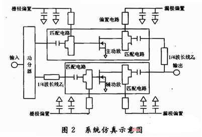
In microwave circuit simulation, ADS software is relatively mature. Here is the use of ADS simulation software to achieve fully matched Doherty power amplifier simulation. Figure 2 is a schematic diagram of the system simulation.

Figure 3 is a simulation result diagram of Doherty power amplifier transmission power gain and efficiency

From the transmission efficiency gain, it can be seen that the amplifier power is 15 dB, its P1dB is 49 dBm, and the P3dB compression point reaches 50 dBm. From the efficiency diagram, it can be clearly seen that the efficiency of P6dB at power backoff reaches 52%, which is much higher than the traditional Class AB amplifier, which fully reflects the advantages of Doherty power amplifier.
3 Doherty power amplifier actual circuit design
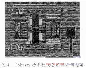
According to the theoretical analysis, the practical application circuit of Doherty power amplifier is designed. The power amplifier chip used by Freescale is used. The specific design circuit is shown in Figure 4.

4 Experimental verification and analysis of test results
For general RF plates, the dielectric constant will change with the temperature change caused by the heating of the amplifier, which will cause the entire circuit loss to be unstable and affect the circuit performance. Therefore, the RF35 type plate is used as the PCB circuit board, and its dielectric constant is relatively stable due to the temperature change caused by the heating of the amplifier during operation. Using a spectrum analyzer and a frequency signal generator to test the power amplifier, the test result is that the Doherty power amplifier has an efficiency of 28% at an output power of 36 dBm, and there is a certain gap between the actual test result and the simulation result. but
Overall, the results are relatively consistent, as shown in Figure 5.

5 Conclusion
Introducing Doherty power amplifier into the front-end transmitter system of digital TV greatly improves the efficiency of the front-end transmitter system. By combining corresponding linearization techniques, such as feedforward technology, the overall performance of the front-end transmitter of digital TV can be made efficient and linear Degree is fully guaranteed. Test results show that Doherty technology can better meet the requirements of modern wireless communication systems for power amplifiers, and will have very broad application prospects.
Wash Motor,Electric Wash Motor,Ac Electric Wash Motor,Washing Machine Motors
WUJIANG JINLONG ELECTRIC APPLIANCE CO., LTD , https://www.jinlongmotor.com