In electronic circuits, power, amplification, oscillation, and modulation circuits are called analog electronic circuits because they process and process continuously varying analog signals.
FeedbackFeedback refers to the change in output being sent to the input in some way as part of the input. If the return part and the original input part are subtracted, it is negative feedback.
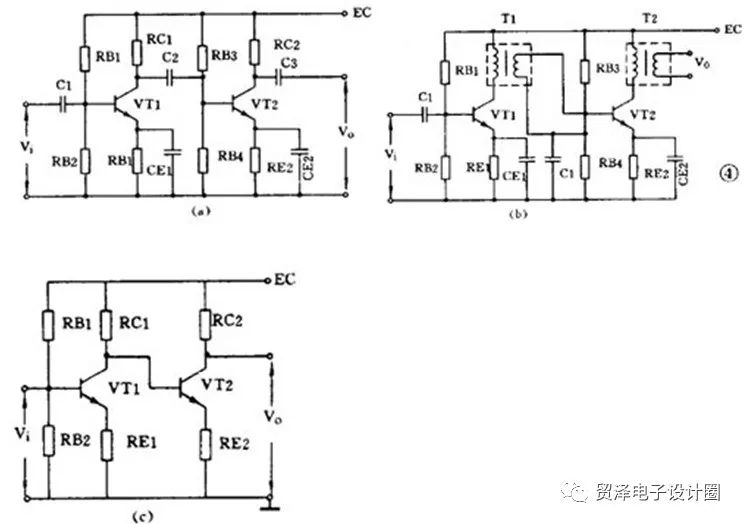
2. CouplingAn amplifier usually has several stages, and the relationship between the stages is called coupling. There are three ways to couple the amplifiers between stages:
1RC coupling (see Figure a): The advantages are simple and low cost. But performance is not optimal. 2 Transformer coupling (see Figure b): The advantages are good impedance matching, high output power and high efficiency, but the transformer is more troublesome to make. 3 Direct coupling (see Figure c): The advantage is the frequency bandwidth, which can be used as a DC amplifier, but the front and rear stage work is pinned, the stability is poor, and the design is more troublesome.
An amplifier that amplifies the input signal and provides sufficient power to the load is called a power amplifier. For example, the final amplifier of a radio is a power amplifier.


The load resistance is a low-impedance speaker, and the transformer can be used to perform impedance transformation, so that the load can obtain a large power.
Regardless of whether there is an input signal or not, the transistor is always in a conducting state, and the quiescent current is relatively large. The collector loss is large and the efficiency is not high, which is only about 35%. This working state is called a Class A working state. Such a circuit is generally used in applications where power is not too large, and its input mode can be either transformer coupling or RC coupling.

The figure below is a commonly used class B push-pull power amplifier circuit.
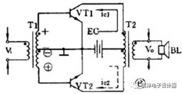
It consists of two symmetrical circuits with the same characteristics. When there is no input signal, each tube is in the off state, the quiescent current is almost zero, and the tube is turned on only when there is signal input. This state is called class B. Working status. When the input signal is a sine wave, VT1 turns on VT2 in the positive half cycle, and turns VT1 off in the negative half cycle. The alternating currents of the two tubes are combined in the output transformer to produce a pure sine wave on the load. This form of alternating operation of two tubes is called a push-pull circuit.

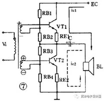
The widely used transformerless class B push-pull amplifier, referred to as the OTL circuit, is a very good power amplifier. For ease of explanation, first introduce an OTL circuit with an input transformer and no output transformer, as shown in the figure below.
A circuit that amplifies a DC signal or a very slow signal is called a DC amplifier circuit or a DC amplifier. This type of amplifier is commonly used in measurement and control.

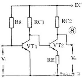
DC amplifiers cannot be coupled with RC or transformers and can only be used in direct coupling. The figure below is a two-stage direct-coupled amplifier. The direct coupling method will bring the mutual control of the front and rear working points. In the circuit, the emitter of VT2 is added with a resistor RE to increase the emitter potential of the latter stage to solve the pinning of the front and rear stages.
Another more important issue with DC amplifiers is zero drift. The so-called zero drift means that when there is no input signal, the static potential changes slowly due to the instability of the operating point. This change is amplified step by step, causing the output to generate a false signal. The more amplifier stages, the more severe the zero drift. Therefore, this double-tube direct-coupled amplifier can only be used in applications where the requirements are not high.

The solution to zero drift is to use a differential amplifier. The figure below shows a widely used emitter-coupled differential amplifier. It uses dual power supplies, where VT1 and VT2 have the same characteristics, the two resistor values ​​are the same, and RE has a negative feedback. In fact, this is a bridge circuit, two RC and two tubes are four bridge arms, and the output voltage V 0 is taken out from the diagonal of the bridge. When there is no input signal, since RC1=RC2 and the two tubes have the same characteristics, the bridge is balanced and the output is zero. Since it is connected into a bridge shape, the zero drift is also small. Differential amplifiers have good stability and are therefore widely used.

The integrated operational amplifier is a device that uses a multi-stage DC amplifier on an integrated chip, as long as a small number of components are externally connected to perform various functions. Because it was used in analog computers as an adder and multiplier in the early days, it is called an operational amplifier.
6. OscillatorA circuit that automatically converts DC power into an AC signal having a certain amplitude and a certain frequency without an external signal is called an oscillation circuit or an oscillator. This phenomenon is also called self-oscillation. In other words, a circuit capable of generating an AC signal is called an oscillation circuit.
An oscillator must consist of three parts: an amplifier, a positive feedback circuit, and a frequency selective network. The amplifier can amplify the input signal applied to the oscillator input to maintain a constant value of the output signal. The positive feedback circuit ensures that the feedback signal supplied to the input of the oscillator is of the same phase, in order to maintain the oscillation. The frequency selective network only allows a certain frequency f0 to pass, allowing the oscillator to produce a single frequency output.
Whether the oscillator can oscillate and maintain a stable output is determined by the following two conditions; one is that the feedback voltage Uf and the input voltage Ui are equal, which is an amplitude balance condition. Second, Uf and Ui must be in the same phase. This is a phase balance condition, which means that it must be guaranteed to be positive feedback. Under normal circumstances, the amplitude balance condition is often easy to do, so in judging whether an oscillation circuit can oscillate, it is mainly to see whether its phase balance condition is established.
The oscillator can be divided into ultra-low frequency (below 20 Hz), low frequency (20 Hz to 200 kHz), high frequency (200 kHz to 30 MHz) and ultra high frequency (10 megahertz to 350 megahertz) according to the oscillation frequency. Kind. According to the oscillation waveform, it can be divided into two types: sine wave oscillation and non-sine wave oscillation.
The sine wave oscillator can be divided into an LC oscillator, an RC oscillator, and a quartz crystal oscillator according to the components used in the frequency selective network. Quartz crystal oscillators have high frequency stability and are only used in demanding applications. In general household appliances, various LC oscillators and RC oscillators are used in large quantities.

The frequency selective network of the LC oscillator is an LC resonant circuit. Their oscillation frequency is relatively high, and there are three common circuits.
1) Transformer feedback LC oscillating circuit
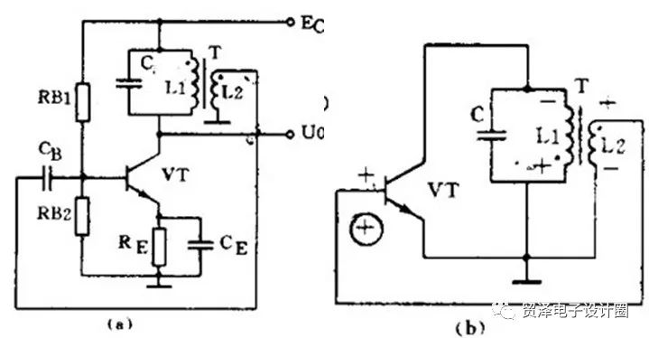
The characteristic of the transformer feedback LC oscillating circuit is that the frequency range is wide and it is easy to start, but the frequency stability is not high. Its oscillation frequency is: f 0 = 1/2Ï€ LC . It is commonly used to generate sinusoidal signals from tens of kilohertz to tens of megahertz.
2) Inductance three-point oscillating circuit
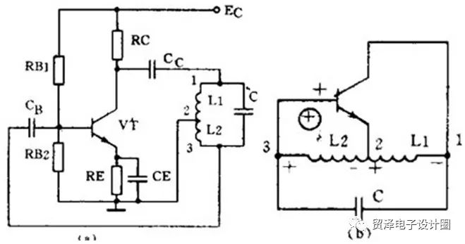
The characteristic of the three-point oscillating circuit of the inductor is that the frequency range is wide and it is easy to start, but the output contains more high-order modulating waves, and the waveform is poor. Its oscillation frequency is: f 0 = 1/2Ï€ LC , where L = L1 + L2 + 2M. Commonly used to generate sinusoidal signals below tens of megahertz.
3) Capacitor three-point oscillating circuit

Capacitor three-point oscillating circuit is characterized by high frequency stability, good output waveform, frequency up to 100 MHz or more, but a small frequency adjustment range, so it is suitable for a fixed frequency oscillator. Its oscillation frequency is: f 0 = 1/2Ï€ LC , where C = C 1 + C 2 .
The amplifiers in the above three kinds of oscillation circuits are common emitter circuits. The oscillator of the common emitter connection has a high gain and is easy to start. It is also possible to connect the amplifiers in the oscillating circuit to a common base circuit form. The oscillator of the common base connection has a relatively high oscillation frequency and good frequency stability.

The frequency selection network of the RC oscillator is an RC circuit, and their oscillation frequency is relatively low. There are two commonly used circuits.
1) RC phase shift oscillating circuit
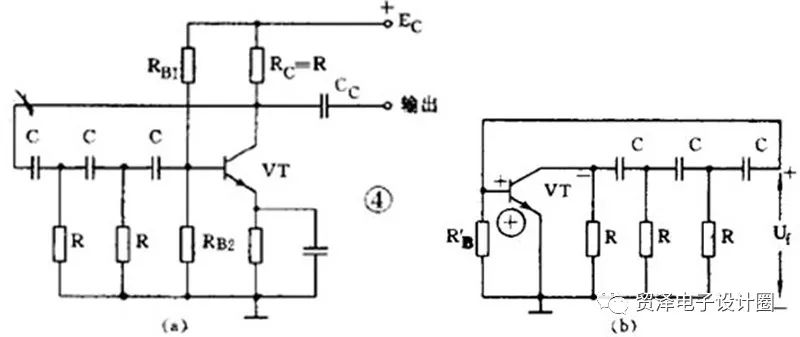
The characteristics of the RC phase-shifting oscillating circuit are: the circuit is simple and economical, but the stability is not high, and the adjustment is inconvenient. It is generally used as a fixed frequency oscillator and where the requirements are not too high. Its oscillation frequency is: when the parameters of the 3-section RC network are the same: f 0 = 1 2Ï€ 6RC . The frequency is generally several tens of kilohertz.
2) RC bridge type oscillation circuit
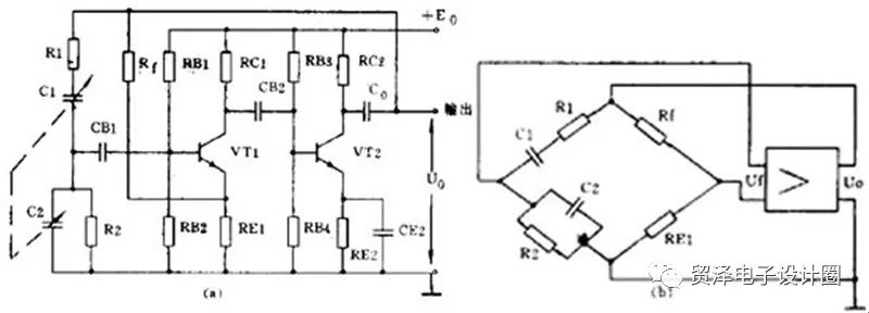
The performance of the RC bridge oscillator circuit is better than that of the RC phase shift oscillator circuit. It has high stability, small nonlinear distortion and convenient frequency adjustment. Its oscillation frequency is: when R1=R2=R, C1=C2=C, f 0 = 1 2Ï€RC. Its frequency ranges from 1 Hz to 1 MHz.
7. AM and detector circuitsBroadcast and radio communications use modulation techniques to apply low frequency sound signals to high frequency signals for transmission. The process of restoring in the receiver is called demodulation. The low frequency signal is called a modulation signal, and the high frequency signal is called a carrier wave. Common continuous wave modulation methods include amplitude modulation and frequency modulation. The corresponding demodulation methods are called detection and frequency discrimination.

Amplitude modulation is such that the amplitude of the carrier signal varies with the amplitude of the modulated signal, and the frequency and phase of the carrier are unchanged. The circuit that can complete the amplitude modulation function is called an amplitude modulation circuit or an amplitude modulator.
Amplitude modulation is a nonlinear frequency conversion process, so its key is to use nonlinear devices such as diodes and transistors. According to which circuit the modulation process is carried out, the triode amplitude modulation circuit can be divided into three types: collector amplitude modulation, base amplitude modulation and emitter amplitude modulation. The following is an example of a collector amplitude modulation circuit.
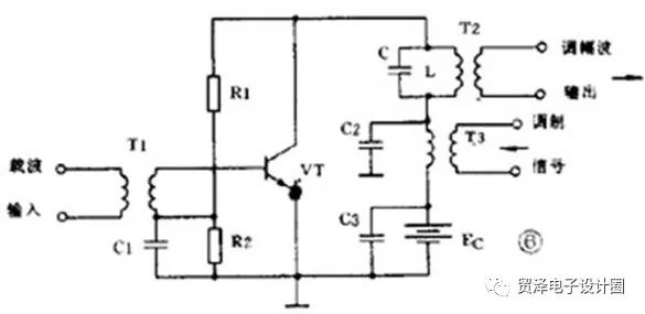

The function of the detector circuit or detector is to extract the low frequency signal from the amplitude modulation wave. Its working process is just the opposite of amplitude modulation. The detection process is also a frequency conversion process, and nonlinear components are also used. Commonly used are diodes and triodes. In addition, in order to extract the low-frequency useful signal, it is necessary to use a filter to filter out high-frequency components, so the detector circuit usually includes a nonlinear component and a filter. The diode detector is taken as an example to illustrate its working principle.

Frequency modulation is to make the carrier frequency change with the amplitude of the modulated signal, while the amplitude remains unchanged. The frequency discrimination is to demodulate the original low frequency signal from the FM wave, and its process is exactly opposite to the frequency modulation.

The circuit that can complete the FM function is called a frequency modulator or a frequency modulation circuit. The commonly used frequency modulation method is the direct frequency modulation method, that is, the method of directly changing the carrier oscillator frequency by using a modulation signal. The picture below shows the general idea, in which a variable reactance element is connected in parallel to the resonant circuit. The variation of the parameters of the variable reactance element is controlled by the low frequency modulation signal to change the frequency of the carrier oscillator.


The circuit capable of performing the frequency discrimination function is called a frequency discriminator or a frequency discriminating circuit, sometimes called a frequency detector. The method of frequency discrimination is usually divided into two steps. The first step is to change the amplitude-modulated frequency wave into a frequency-modulated frequency-frequency-modulating wave. The second step uses a general detector to detect the amplitude change and restore it to a low-frequency signal. Commonly used frequency discriminators include phase discriminators, proportional discriminators, and the like.
Outdoor Mobile LED Kiosk Poster
The Best Advertising choice and the best money earning machine--Outdoor LED screen kiosk
Outdoor Led Kiosk Poster also called led AD Kiosk player is one of new applications for led displays. Developed from led screens, it is more suitable and friendly to operate. Don't need to install as it is floor standing. and could be put anywhere it needed indoor or outdoor environment.
Optional Pixel Pitch 4mm,5mm,6mm.optional sizes 60`'.IP65/54, weather proof; Ultra Outdoor HD led display Kiosk poster, crystal clear and vivid images; High brightness and auto adjustment according to environment; Intelligent group management, easy and convenient. Thanks to the Cluster controll system and GPS technology, no matter how many posters you have where they are, you could controll them easily and change content quickly.
They are one of none stop money earning machines!
Intelligent monitoring and GPS
High brightness for outdoor and energy saving
Outdoor Mobile Led Poster,Mobile Led Poster,Outdoor Display Of Mobile Led Poster,Led Screen Of Window Signage
Shenzhen Priva Tech Co., Ltd. , https://www.privaled.com