Overview:
The UCD92xx-based non-isolated digital power system consists of a control chip and a power stage chip. The power stage chip consists of Mosfet driver and power Mosfet, including a stand-alone Mosfet driver (such as UCD7232), or a power stage chip integrated with Mosfet (such as UCD7242 and UCD74120). Fusion Digital Power Designer, an online tool used with the UCD92xx, can adjust the feedback loop online to improve loop regulation efficiency. This article demonstrates how to adjust the loop online on a digital power board based on the UCD9224 and UCD74120.
1. Introduction To design a non-isolated digital power supply based on UCD92xx, you need to first select the appropriate control chip and power stage chip. When the UCD74120 is selected for the power stage chip, the driver and the BUCK upper and lower tubes are integrated inside, and the inductor and output capacitor need only be added to the periphery. The entire power system can then be configured and adjusted using online software tools.
1.1 Digital Power Controller UCD92xx
UCD92xx is a non-isolated digital power controller with integrated ARM7 core. It can be flexibly configured in multi-channel or multi-phase mode. Take UCD9224 as an example, it can be configured as dual output or single-channel four-phase parallel output.
Figure 1 is an internal block diagram of the UCD9224. Key modules include:
â— Fusion Power Peripheral: includes output voltage error acquisition, loop compensation, and DPWM output.
â— ADC sampling module: contains 10 ADC interfaces for collecting external information (such as temperature, current) and internal information (temperature);
â— Analog Comparators module: Contains three analog comparators for fast protection against overcurrent faults;
â— ARM-7 module: including ARM-7 core, Flash and crystal oscillator;
â— PMBUS module: communication interface, used to communicate with the host computer;
â— Other: Includes modules such as SRE control to control whether the BUCK operates in synchronous rectification or non-synchronous rectification mode; 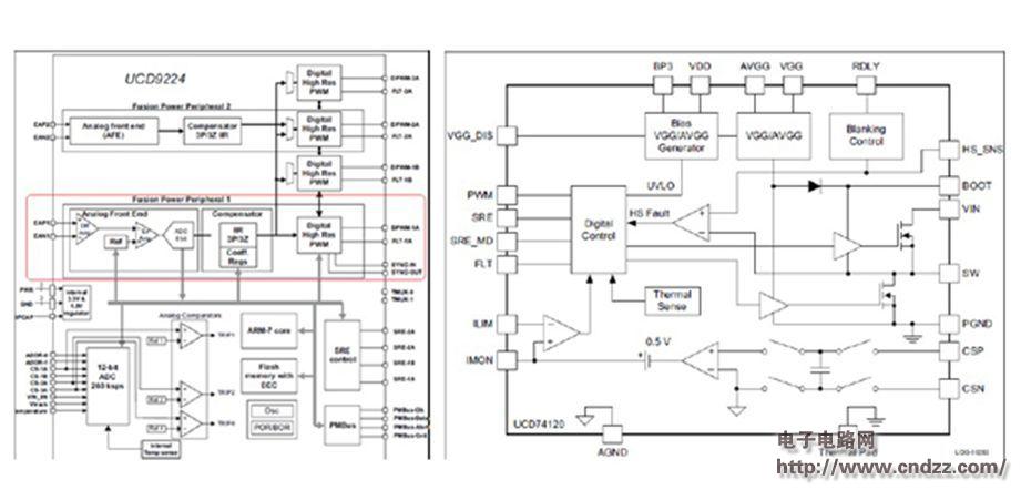
Figure 1: Internal Block Diagram of UCD9224 Figure 2: Internal Block Diagram of UCD74120 (Please read the PDF for details)
A Brushless DC Electric Motor (BLDC motor or BL motor), also known as electronically commutated motor (ECM or EC motor) and synchronous DC motors, are synchronous motors powered by direct current (DC) electricity via an inverter or switching power supply which produces an alternating current (AC) electric current to drive each phase of the motor via a closed loop controller. The controller provides pulses of current to the motor windings that control the speed and torque of the motor.
The construction of a Brushless Motor system is typically similar to a permanent magnet synchronous motor (PMSM), but can also be a switched reluctance motor, or an induction (asynchronous) motor.
The advantages of a brushless motor over brushed motors are high power-to-weight ratio, high speed, electronic control, and low maintenance. Brushless motors find applications in such places as computer peripherals (disk drives, printers), hand-held power tools, and vehicles ranging from model aircraft to automobiles.
24v brushless motor,24v brushless dc motor,24 volt brushless motor,Brushless dc motor 24v 500w
Shenzhen Maintex Intelligent Control Co., Ltd. , https://www.maintexmotor.com