introduction
This article refers to the address: http://
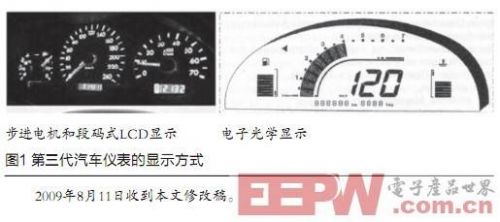
The automobile instrument is composed of various instruments and indicators, especially the driver's warning lights and alarms, and provides the driver with the required vehicle operating parameter information. According to the working principle of automobile instruments, it can be roughly divided into three generations. The first generation of automotive instrumentation is a mechanical movement watch; the second generation of automotive instrumentation is called an electrical instrumentation [1]; the third generation is an all-digital automotive instrumentation, which is a networked, intelligent instrument that is more powerful. The display content is more abundant, and the wire harness connection is simpler.
Most of the current automotive instruments are third-generation instruments. They can use A/D conversion or digital pulses to obtain data directly from the sensor. They can also use the CAN bus to obtain data through the vehicle network. It can drive the instrument pointer through a stepper motor. You can also use the LCD screen to display graphical or textual information directly. At the same time, it has an intelligent processing unit that can exchange information with other control units of the car. 
Overall demand and design
The function of the car instrument is to get the data you need and display it in a suitable way. Previous meters were generally limited to 3 to 4 displays and 4 to 5 warnings. The new meters now have about 15 displays and about 40 warnings. The main reasons leading to the rapid growth of instrument display information are as follows: [2]:
â— New features on the car continue to increase, such as ABS, airbags, parking sensors, etc.;
â— A more real-time understanding of the state of the car, such as tire pressure, water temperature, fuel consumption, etc.;
â— More detailed control of the working conditions of various parts of the car, such as lighting, doors, locks, seat belts, etc.
Different information has different ways of obtaining and displaying. At present, there are three main ways to obtain new instrument information:
â— Transmission via the body bus;
â— Converted by A/D sampling;
â— Obtained by IO state change.
For the display mode, there are mainly five ways: by driving the stepper motor to drive the pointer to rotate; by the dot matrix LCD screen to display graphic or digital information; by the segment LCD screen or digital tube display; by the LED light switch display; by buzzing Different beeps indicate the current status.
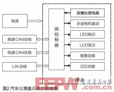
According to the above requirements, the car dashboard node designed in this paper consists of MCU system, stepper motor drive, LED display, LCD display, alarm function, memory function, button processing, LIN bus communication, high speed CAN communication, low speed fault tolerant CAN bus communication and power supply. Supply and other aspects constitute (Figure 2). 
Hardware circuit design
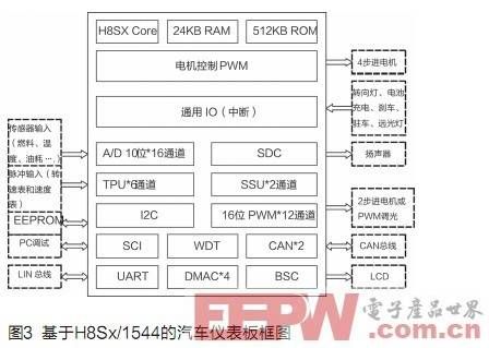
H8Sx/1544 is a chip that fully meets the needs of the third generation of automotive instrumentation. It has a 32-bit MCU with high-speed computing capability, two CAN channels, and can directly drive stepper motors and LCD modules. The performance parameters meet the automotive industry level. Request [3]. Peripheral modules include stepper motor control PWM timer, LCD module interface, 16-bit timer pulse unit (TPU), DMA controller (DMAC), CAN bus controller, serial interface, A/D converter, warning light and Alarm output, LED PWM dimming, etc. These modules can meet the signal acquisition and display of vehicle speed, speed, oil quantity and cooling water level, and can easily realize the dashboard circuit with few external components [4]. The block diagram of the car dashboard based on H8Sx/1544 is shown in Figure 3. 
The 6 sets of stepper motors can be directly driven by the PWM pins of the H8Sx/1544 to indicate the vehicle speed, engine speed, coolant temperature, fuel tank fuel quantity, oil pressure and generator voltage. The dot matrix liquid crystal module with parallel 8080 interface can be directly connected to the MCU for displaying graphics and other information. High-speed CAN and low-speed CAN are respectively connected to two CAN networks in the car, and can be used as a gateway if necessary. The vehicle speed sensor and the engine speed sensor usually use a Hall device. In order to improve the waveform, a Schmitt circuit is used for shaping outside the input capture timer pin.
software design
In order to improve the reusability, readability and maintainability of the code, the basic idea of ​​software writing is to standardize and modularize the application software as much as possible while satisfying the system function. Each module is a program with independent functions that can be individually designed, debugged and managed.
The software module mainly includes a main program module, an initialization module, a data acquisition module, a stepping motor drive module, a CAN communication module, a LIN communication module, an SPI communication module, a display module, a storage memory module, an alarm module, an interrupt module, and the like.
The alarm module realizes the control alarm signal output under abnormal conditions. If the temperature of the coolant rises near the boiling point or the fuel quantity in the fuel tank is less than a certain value, the audio alarm will issue an alarm signal of different frequencies to illuminate the indicator light. The interrupt module has four kinds of interrupt sources: button signal, wheel speed signal, engine speed signal and power-down protection signal, which respectively complete the panel function setting, speed measurement and data saving when power is off. The data acquisition module samples and quantizes the corresponding analog signal according to the input parameters, and performs anti-interference processing on the sampled signal. The display module completes the initialization of the LCD and displays various required symbols and values. The stepping motor drive module drives the stepping motor in a micro-step mode, and has three modes of acceleration, uniform speed and deceleration to overcome the phenomenon that the motor lags and stops when starting.
Conclusion
Through the analysis of the basic functions of the automobile instrument system, this paper completed a high-integration, embedded, bus-based automotive combination electronic instrument. The instrument can realize the real-time indication of the dial pointer driven by the stepping motor and the graphical display of the LCD, and achieve the design requirements of low power consumption, strong fault tolerance and high modularity. The combined electronic instrument has high precision, good linearity, fast response, strong adaptability, accurate recording and stable performance, and all aspects of performance have reached the domestic leading level.
Battery Online Monitoring System
Multifunctional Battery,Read Data And Information Battery,Safety Monitoring System Battery,Custom Monitoring System Battery
Wolong Electric Group Zhejiang Dengta Power Source Co.,Ltd , https://www.wldtbattery.com