introduction
This article refers to the address: http://
In the past, smart car races were divided into photoelectric groups and camera groups. The photoelectric group mainly used photoelectric sensors such as infrared sensors to collect path information, and the camera group mainly identified paths by collecting image information. In this paper, the electromagnetic vehicle is guided by the electromagnetic field generated by the energized wire. The advantage of using the magnetic field signal to guide the vehicle to travel along a certain trajectory is mainly reflected in the good environmental adaptability of the magnetic field signal, and is not affected by environmental factors such as light, temperature and humidity.
Design principle
According to electromagnetics, we know that a constant current (such as a current that changes according to a sinusoidal law) is applied to a wire, and a varying magnetic field is generated around the wire, and the magnetic field and the current change are consistent. If an inductance consisting of a coil is placed in the magnetic field, an induced electromotive force is generated on the inductance, and the magnitude of the induced electromotive force is proportional to the rate of change of the magnetic flux passing through the coil loop. Since the magnitude and direction of the magnetic induction are different at different locations around the wire, the induced electromotive force generated by the inductance at different locations should also be different. According to this, the approximate position of the inductance can be determined.
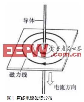
First of all, it is known from Biot-Savar's law that a magnetic field is generated around a straight wire having a constant current I of length L, and the magnetic induction intensity at a point P from the distance of the wire is:
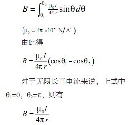
And the direction of the magnetic induction is perpendicular to the paper facing. Thus, its magnetic field lines are a series of concentric circles with the wire as the axis in a plane perpendicular to the wire, and the magnetic induction intensity on the circle is the same.
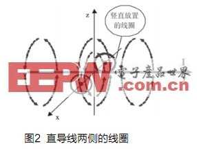
For the curved wire with current, according to Biot-Savar's law, it can be concluded that the magnetic line density on the inner side of the arc is larger than the outer side of the arc. If two coils in the same direction as the current are placed vertically above the two sides of the energized straight wire and the curved wire, as shown in Fig. 2, the magnetic flux is passed through the two coils.
When the current in the wire changes according to a certain law, the magnetic field around the wire will also change, and a certain electromotive force will be induced in the coil. According to Faraday's law of electromagnetic induction, the magnitude of the induced electromotive force is proportional to the rate of change of the magnetic flux through the conductor loop:

The direction of the induced electromotive force can be determined by Lenz's law. Since the current passing through the wire in this design is low, 20 kHz, and the coil is small, the distance from the center of the coil to the wire is r, and the magnetic field distribution in the small range is considered to be uniform, and the induced electromotive force in the coil can be approximated as follows:

That is, the magnitude of the induced electromotive force in the coil is proportional to the rate of change of the current, inversely proportional to the distance from the center of the coil to the wire. Where k is an amount related to the coil placement method, coil area, and some physical constants. The specific induced electromotive force must be determined by actual measurement.
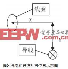
In this design, the coil is placed vertically along the direction of the current, because the magnitude of the induced electromotive force generated in the coil (shown in Figure 4) with a horizontal distance x from the wire placed at h above the wire is ![]() In proportion, where q is the angle between the plane of the sensor and the wire. Since the body may be at an angle to the wire, q is not necessarily zero.
In proportion, where q is the angle between the plane of the sensor and the wire. Since the body may be at an angle to the wire, q is not necessarily zero.
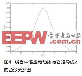
Figure 4 is the relationship between the induced electromotive force in the coil drawn in q = 0o, h = 5cm and the horizontal distance x of the wire. It can be seen that the induced electromotive force distribution in the vertically placed coil is simple, the attenuation is fast, and the distance is near. The interference is small and is very suitable as a sensor to detect the current position of the car.
For straight conductors, when the trolleys with the two coils with the central axis of the trolley are traveling along their straight lines, that is, when the positions of the two coils are symmetrical with respect to the conductors, the magnitude of the electromotive force induced in the two coils should be the same, and the direction is also the same. If the car deviates from the straight wire, that is, if the two coils are asymmetrical about the wire, the magnetic flux passing through the two coils is different. At this time, the electromotive force induced in the coil closer to the wire should be greater than that in the coil farther from the wire. Based on the difference between the two asymmetric signals, the direction of the trolley can be adjusted to guide it in a straight line.
For a curved wire, that is, a turning point of a path, since the density of magnetic lines on both sides of the arc is different, when the trolley carrying the coil travels there, the electromotive force induced by the coils on both sides is different. Specifically, the induced electromotive force of the inner coil of the arc is larger than the outer coil of the arc, and the signal can guide the turning of the trolley.
In addition, when the trolley is driven away from the wire so that the two coils are on one side of the wire, the induced electromotive force in the two coils is also unbalanced. The electromotive force induced in the coil closer to the wire is larger than the coil farther from the wire. Thereby, the trolley can be guided back to the wire.
Due to the closeness and directivity of the magnetic induction line, the direction of change of the magnetic flux passing through the two coils is uniform, that is, the induced electromotive force direction is the same, so the above analysis can compare the magnitude of the induced electromotive force generated in the two coils to determine the trolley. With respect to the position of the wire, an adjustment is made to guide the car to travel substantially.
Design
This design uses a common toy car as the car model, which is driven by PWM signal. When the PWM signal pulse width is in the range of (1ms, 1.5ms), the steering gear controls the car to drive to the left. When the pulse width is (1.5ms, 2ms), the car is turned to the right. When driving, the car travels in a straight line when the pulse width is about 1.5ms. This solution uses two 10mH inductors placed on the head of the car as a sensor to determine the position of the car. Then, an analog circuit is designed to acquire, condition, and amplify the electromotive force signal obtained by the inductor. The specific circuit is shown in Figure 5.
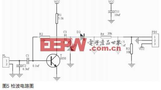
The circuit uses a voltage parallel negative feedback circuit, and the inductive signal enters from the PL. Considering that the electromotive force induced by a single inductor is small, this design uses an inductor and a capacitor to amplify the induced electromotive force. Since a 10mH inductor is used, the current frequency in the wire is 20kHz, so a 6.3nF capacitor is used. In this way, the voltage obtained on the capacitor will be relatively large, which is convenient for the triode to amplify. The specific magnification of the entire circuit needs to be calculated based on the actual load. The trolley control circuit of this design is shown in Figure 6.
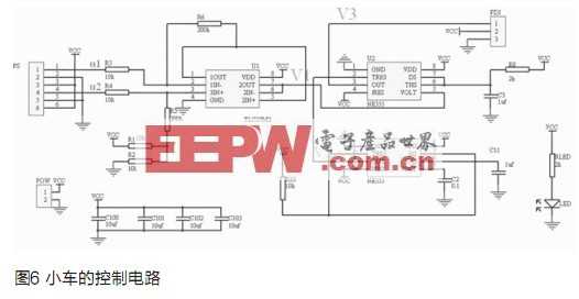
First, the voltage outputs u1 and u2 obtained by conditioning and amplifying the induced electromotive force obtained by the two inductors are sent to a subtractor composed of an operational amplifier for subtraction, and then sent to the lower by a voltage follower composed of an operational amplifier. Primary circuit. After analysis, the output of this stage of the circuit can be roughly calculated by the following formula: ![]()
The latter stage circuit consists of two 555 timers, with the lower 555 forming a pulse generator with a duty cycle very close to 1, acting as a trigger for the upper 555. Because the low-level signal of this trigger pulse is very narrow, it can well ensure the normal operation of the monostable circuit formed by the upper 555. The waveform is shown in Figure 7. The pulse signal frequency is:
![]()
The upper 555 timer forms a one-shot voltage-controlled oscillator whose pulse width is controlled by input V1 and the output is the PWM signal. When V1 is large, that is, when the induced electromotive force in the two inductor coils is large, that is, when the trolley is traveling to the left from the wire, the pulse width is large, and the steering gear will control the car to drive to the right; when V1 is moderate, Close, that is, when the trolley travels along the wire, the pulse width is close to 1.5ms, and the trolley runs in a straight line; when the V1 is small, that is, when the trolley deviates from the wire to the right, the pulse width is small, and the steering gear will control the trolley to drive to the left. Thus, the control car travels roughly along the wire. In addition, by changing the value of the resistors constituting the subtractor, the sensitivity of the reaction of the trolley can be adjusted, thereby preventing the phenomenon that the trolley swings left and right with the wire as the central axis.

mobile phone screen protector,9H hardness film,HD glass screen protector
Guangdong Magic Electronic Limited , https://www.magicmax.cc