Overview:
The main features of the power supply
1. The output voltage is continuously adjustable from zero, the maximum output voltage is 20V, and the output current can reach 1A;
2. The maximum output current is limited. There are two options: l00mA and 1A, and the output limit current can be set as required (from 0 to 100mA or 0 to 1A) to ensure the safety of the circuit.
3. The power supply responds quickly and remains stable at different output voltages and output currents;
4. Output voltage and output current indication (two pointer type heads) and exceeding limit current indication (LED);
5. Because it has adjustable voltage output and limited current output, it can be used as a charger (such as lead-acid battery) and can prevent overcharging.
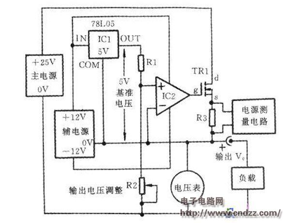
The power circuit is more complicated, and its core part is the output voltage control circuit. The block diagram of the control output voltage is shown in Figure 1. The circuit uses two power supplies: one is a 25V/1A main power supply; the other is a ±12V/100mA auxiliary power supply. The main power supply supplies the load output voltage and output current. The auxiliary power supply is used for the control circuit and the output voltage starts from 0V. The working principle is as follows: the reference voltage is generated by ICl (78L05) and the resistor R1, and the error amplifier (op amp IC2) is normal. In operation, feedback is used to maintain the non-inverting terminal potential equal to the output voltage Vo.
The voltage at the output of IC1 to the negative terminal of the power supply terminal is Vo(78L05)=Vo+5V. Since VRl=5V is constant, IR1 is a constant current. When this current flows through R2, changing the value of the variable resistor R2 linearly adjusts the output voltage.
This can be seen as the "0V" of the auxiliary power supply is floating relative to the negative terminal (0V) of the main power supply. Changing the value of R2 can change the "0V" of the auxiliary power supply up and down: when R2=0, "0V" and the main power supply The negative terminal (0V) coincides and the output voltage is 0V. When R2 is adjusted to the maximum, “0V†is 20V to the main power supply negative terminal (0V), and the output voltage is 20V. However, the ±12V of the auxiliary power supply is constant with respect to "0V". It always supplies the IC2 power supply, so that IC2 controls the adjustment tube TR1 to keep the output voltage Vo stable.
In the figure below, the voltmeter is connected across the OV terminal of the main and auxiliary power supplies to indicate the output voltage Vo. R3 is the sense resistor for detecting the load current, and VR3 is proportional to the load current Io.

(Please read the PDF for details)
Smart Watch,Smart Watch Women,Sport Smart Watch,Heart Rate Smart Watch
GANSU PINGLINAG ABAY SCIENCE&TECHNOLOGY CO.,LTD , https://www.yzwtech.com