Almost all mobile terminals use small antennas. Its disadvantages are low efficiency and narrow bandwidth. In order to ensure the performance of the antenna, there is a certain limit to the miniaturization of the antenna. However, this goes against the trend of the era of miniaturization of mobile terminals. Fortunately, most of the components used in antennas are conductors that can create space. Compared with the wavelength, as long as the conductor has a certain size, it can basically be used as a high antenna. For example, structures such as mobile terminal housings meet the above conditions (Figure 1).
At present, most mobile terminals use frequencies between 800mMHz and 2GHz, and the wavelength is equivalent to about 150-350nm. Therefore, a terminal size of 100-200mm is very beneficial for small antennas. That is to say, as long as the chassis of the mobile terminal is used cleverly, it can be obtained. Small, high-performance antenna function. In view of this, this article uses the case of a mobile terminal as an antenna as an example, and introduces the design techniques of antennas for digital playback on the ground and diversity antennas for PDC (Personal; Digital Cellular).
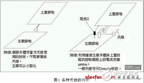
As mentioned above, low efficiency and narrow bandwidth are the main disadvantages of general small antennas. The specific bandwidth of an antenna (the frequency range defined by the center frequency) is closely related to the size of the antenna, and the bandwidth of a small antenna is proportional to the volume of the antenna. The efficiency of the antenna can be expressed by the following formula:
η=Pr/(Pr+Pd)
η: the efficiency of the antenna.
Pr: Radiation power.
Pd: Lost power.
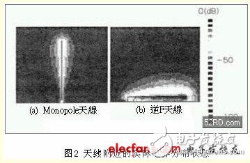
It can be seen from the above formula that if the size of any small antenna is reduced, Pr will be smaller than Pd and the radiation efficiency will be greatly reduced. This phenomenon is especially obvious in the electromagnetic field near the antenna. Figure 2 shows the actual electrical distribution near the antenna when the same power is supplied to the two antennas. The height of the monopole antenna in the figure is λ/4 (where λ represents the corresponding wavelength of the antenna frequency), which is a medium-sized antenna At this time, the maximum intensity of the monopole antenna is about -20dB; in contrast, the height of the inverse F antenna is λ/10, which is a small antenna. At this time, the maximum intensity of the F antenna is only 0dB. It can be seen that even the same power varies with the size of the antenna. The electric field (voltage) distribution state near the antenna is completely different, and the same magnetic field, that is, the current intensity is also different. For a small antenna, if the conductor and the space around the antenna are lossy media, it will cause a huge loss of power (power), and the relative efficiency will also be rapidly degraded.
The equalized G and physical length L of the antenna can be expressed by the following formula: G=8log (2L/λ) (dBd) (dBd) is the intensity (compared with half-wavelength Dipole) when receiving radio waves. Here, if the antenna of a mobile terminal with a frequency of /20nm is substituted into the above equation, a (theoretical) efficiency of about -7.7dB can be obtained, but in fact the efficiency of the mobile terminal is only about -1dB.
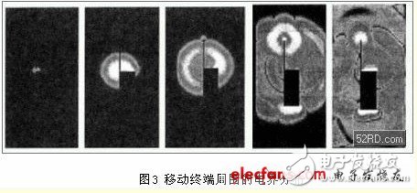
Figure 3 shows the distribution of electrical boundaries around the mobile terminal. It can be seen from the figure that if pulsed electrical boundaries are applied to the antenna, the electrical boundaries around the antenna will change over time. The boundary strength will also increase with time. In other words, as long as the radio wave radiation characteristics of the mobile terminal chassis are used cleverly, even a small antenna can achieve the desired effect.
Generally, digital surface wave broadcasting uses a UHF (UltraHigh Frequency) bandwidth with a wavelength of 400~600nm. However, in fact, physical limitations make it difficult for the antennas of traditional mobile terminals to be miniaturized. Therefore, the mobile terminal housing is changed to extraction or Fold the design to form a direct excitation antenna on the right side of Figure 4.
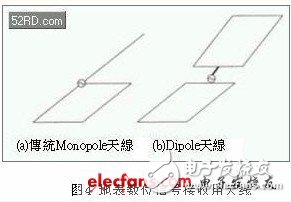
Next, the radiation pattern in the horizontal plane of the above two antennas is actually tested in the anechoic chamber. It must be noted that the characteristics of the antenna are easily affected by the use environment including the human body. Therefore, the tested antenna must be far away from the human body during the test. In addition, the radio waves are almost Incident from the horizontal direction, so this test is based on the radiation pattern in the horizontal plane as the discussion object.
Figure 5 shows the test results of each antenna in an anechoic chamber; Table 1 uses the equalized average value of the Dipole antenna as a comparison benchmark. The calculation results in Table 1 show that the traditional Monopole antenna and the Dipole antenna have the same degree of -2.5~2.8dB The average equalization value of.
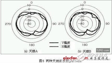
Carry out the outdoor test according to the above test results, and do the receiving and transmitting test in two fields during the test. In the dark room test, the tested antenna rotates a circle away from the human body, and the average receiving power of the antenna is calculated based on this; compared with the outdoor test, the tested antenna is walked for about ten minutes in a roundabout distance, and then the Dipole antenna is used as the antenna. Compare the benchmark and calculate the average receiving power of the antenna. According to the calculation results in Table 1, the average receiving power of the two antennas in the four venues is almost the same, which is consistent with the test results in the above-mentioned anechoic chamber. This proves that as long as the radio wave radiation characteristics of the mobile terminal chassis are used cleverly, even Small antennas can also achieve the desired effect.
Table 1 Equalization characteristics of each antenna

In order to suppress the deterioration of communication quality caused by fading, mobile communication systems usually use Diversity antennas. The two Diversity antennas introduced in the previous section are mainly designed for reception purposes, so they involve the installation location and antenna structure of the antenna.
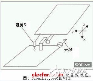
Here, an impedance (Impedance) Z is added to the folding chassis of the mobile communication system, so that a variety of radiation patterns can be obtained with one antenna. The biggest advantage of this design is that it can greatly reduce the antenna installation location and the antenna structure. size.
Figure 6 is the structure of the Diversity antenna. As shown in the figure, the antenna is set in the center of the two grounds of the folding chassis. The signal line and the impedance of the side-by-side connection are laid between the two grounds, and then the impedance is changed to observe the radiation pattern. According to the test results in Figure 7, when Z=Z0 (open) and Z=Z1 (volume), the radiation pattern changes significantly. When Z=Z0, the radiation pattern shows a lateral figure of eight, and when Z=Z1, the radiation pattern and Z =Z0 is completely different. In other words, even with the same antenna, different radiation phenomena will appear as Z changes.
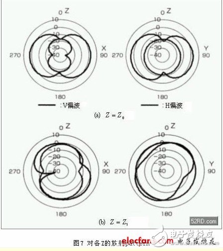
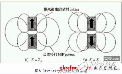
In order to explore the changing principle of the radiation pattern, current is applied to the casing to observe the current distribution characteristics. According to the test results in Figure 8, the upper and lower casings have the same phase current flow when Z=Z0, and it is the same as the radiation pattern in Figure 7. They are all in the shape of a lateral figure eight. Since Z=Z0 is the same-phase current, the electrical boundary is added laterally; the opposite Z=Z1 becomes a reverse-phase current, so the electrical boundary offsets each other laterally, and the overall radiation pattern is Butterfly wings. It can be seen that as long as the impedance Z is changed, the current on the chassis can be controlled and the radiation pattern generated by the current can be changed.
The above introduces the use of the mobile terminal case as a conductor to design small high-performance antennas. At the same time, it discusses the design techniques of antennas for digital broadcasting on the ground and diversity antennas for PDC (Personal Digital Cellular).
15v wall charger,15 Watt Power Supply,15v ac dc adapter,AC Wall Charger Power Adapter,AC/DC Charger Power Supply Switching Adapter,DC 15V Global AC / DC Adapter,15VDC Power Supply Cord Cable Wall Charger,15VDC800 Charger PSU
Shenzhen Waweis Technology Co., Ltd. , https://www.waweis.com