Detailed explanation of the matching of the power amplifier of the mixer
Matching of the power amplifier The best working state of the power amplifier is the matching before and after, that is, the input terminal should match the signal source, and the output terminal should match the speaker load RL. In this case, the power efficiency of the power amplifier can be fully exerted, the power amplifier can run reliably for a long time, the transmission power is high, and the acoustic signal is not distorted. The matching of the general input terminal is relatively simple, and the output impedance of the signal source is usually around 600Ω. The input impedance of the power amplifier is mostly above 10kΩ. Obviously, most of the output signal of the signal source can be input to the pre-amplifier stage of the power amplifier. The output of the power amplifier is the power signal of the sound. These power signals can be effectively transmitted to the speaker without distortion and converted into sound. Here, the matching problems in the following aspects are involved.
1. The impedance matching regards the power amplifier as an equivalent circuit. Its output impedance is R0 and the speaker load RL forms a current loop. The acting voltage U on the loop, the voltage on the load RL is the output voltage U.
Under what circumstances can the power obtained on the load achieve the maximum power at both ends of the load? Obviously, taking W as a function and RL as a variable, and finding the extreme value of W, you will get R0 = RL, W is the largest, that is to say, the speaker should obtain the maximum power output of the amplifier, the condition is: the speaker load impedance should be Equal to the output impedance of the power amplifier. If the load impedance of the speaker is greater than the output impedance of the power amplifier, the power of the power amplifier cannot be transmitted well, resulting in an increase in internal heat, affecting the working stability of the power tube, or even being damaged due to overheating. If the load impedance of the speaker is less than the output impedance of the power amplifier, the output power signal is distorted, the power consumption inside the power tube rises sharply, and it will overheat and burn. Therefore, the power amplifier can operate normally only if the above impedance matching conditions are satisfied.
2. Power matching Under the condition that the power amplifier impedance matching is met, if the power output of the power amplifier is greater than the rated power of the speaker for long-term reliable operation, although the speaker can get the maximum power, it will inevitably cause the speaker voice coil to heat up and the mechanical performance is destroyed. If the output power of the power amplifier is less than the rated power of the speaker, the sound output power of the speaker cannot be fully exerted, and the sound output frequency band may be narrowed and the radiated sound may be unbalanced. Therefore, the output power of the power amplifier must be equal to the rated power of the speaker. That is, the working power of the amplifier is equal to the rated power of the speaker, which is the matching condition of the amplifier power. The power amplifier often runs under the music signal, and the ups and downs of the music signal are very large. In terms of general music, the peak power of the music is 4 times the rated power of the power amplifier. In order to make the power amplifier operate reliably for a long time, the power amplifier must be left working. There is a reserve, the reserve of the power amplifier is defined as:
The maximum undistorted power P0 of the power amplifier is defined as: under the condition that the total harmonic distortion is not greater than 1% when the load is 8Ω, the continuous sine wave power output by the power amplifier. The rated power of the power amplifier is half of the maximum undistorted power of the power amplifier, that is, P0 / 2; the reserve capacity of the power amplifier can be 3 to 8, if it is 3, the working power of the power amplifier can be obtained = 2/3 × the rated power of the power amplifier , Also equal to the rated power of the speaker. This relationship can be used as the relationship between the rated power of the speaker and the rated power of the power amplifier.
3. The load of the damping factor power amplifier is not a pure resistance, but a speaker voice coil. The voice coil has a certain inductance and is an inductive load. Its impedance value is related to the signal frequency. Whether the output signal can be well transmitted involves the output circuit. Damping problem, the damping factor (or damping coefficient) is defined as: speaker load impedance / internal resistance of the power tube (including wiring resistance), the larger the ratio, the faster the vibration damping of the speaker, the more stable the power tube working state, usually Greater than 200: 1.
Notes on using the power amplifier The power amplifier itself has few operation function keys, and the operation is extremely simple. Usually, as long as the power switch is turned on, the work can be performed. But it is connected to the signal source in front of it, and the speaker load is connected to the back. Improper operation before and after is very harmful to the power amplifier. Therefore, the following points should be paid attention to when using it:
(1) In the sound reinforcement system of the power amplifier, when switching on, first turn on other audio equipment, and finally turn on the power amplifier. When shutting down, turn off the power amplifier first, then turn off other equipment. In this way, you can avoid the pulse signal generated by turning on and off other audio equipment, overloading the amplifier, and burning the amplifier or speaker.
(2) When the power amplifier is working, the volume (controlled on the mixer) is from small to large, until it is moderate. When turned off, the volume (controlled on the mixer) changes from large to low, and then turns off.
(3) During the working process of the power amplifier, the working mode or speaker load of the power amplifier cannot be arbitrarily changed, otherwise the power amplifier may be easily damaged. Usually, the working mode of the power amplifier is determined first, and the speaker load is connected according to the working mode.
(4) During the working process of the power amplifier, the plugs of various audio equipment in the sound reinforcement system, including the plug of the mixer, cannot be arbitrarily replaced. Otherwise, it is easy to generate a pulse signal, and a power pulse is formed after the power amplifier until it is directed to the high-frequency head of the sound, causing the high-frequency head to burn or overload the power amplifier to be damaged.
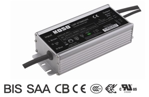
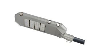
MOSO dimmable LED Driver is designed for various types of exterior or industrial LED lighting, including LED roadway lighting, LED street lighting, LED flood lighting, LED highbay lighting, LED high mast lighting, LED architecture lighting, etc. The driver is compliant to all 0~10V and PWM dimming controllers, dimming systems, and smart control systems.
All dimmable LED Drivers comes with compact size and IP67 protection. So the same driver can be used for independent or built-in a waterproof power supply chamber. There is no limitation of the IP rating of the luminaire housing.


The ProgrDimmable LED Driver operates in constant current model. There are two types dimmable LED drivers available in MOSO: 1) Programmable Dimmable LED Driver, or constant current dimmable LED driver.
A programmable dimmable LED driver can be monitored by an infrared-based programming device, to deliver different output current and voltage values to LED modules. With one driver, you can use it for different light fixture designs. The fully programmed drivers offer all dimming options (0-10V/PWM/Timing
control/DALI) and a wide range of output current in a single driver, which
deliver maximum flexibility with customized operating settings and intelligent
control options for lighting manufacturers. The Programmable dimmable LED drivers obtained many global safety certifications,
including UL, CE, TUV, ENEC, CB, SAA, BIS, KC, etc, they are compatible with the safety regulations
in different countries.
A constant current dimmable LED driver will only deliver fixed output current, you are not able to change the Iout like a programmable driver. The driver is competible with 0-10V / PWM / DALI dimming prootcols.
The compact metal case and high efficiency enables the power supply to operating with high reliability, and extending product lifetime to at least 50,000 hours. Overall protection is provided against lightening surge, output over voltage, short circuit, and over temperature, to ensure low failure rate.
MOSO grants the product with 5 years global warranty. Customer can refer to Warranty policy, find the closest MOSO distributors or sales representatives, to get a local replacement in case of any failure.
Dimmable LED Driver
Dimmable LED Driver,Dimmable LED Lighting Driver,Dimmable Slim LED Driver,Dimmable Tunnel Light LED Driver
Moso Electronics , https://www.mosoleddriver.com