Way 1
When M0=0 and M1=0 in TMOD, it is a 13-bit counting or timing mode, among which TLi uses the lower 5 bits, and its structure is shown in Figure 4.2.
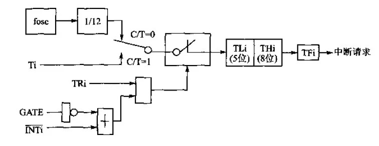
Figure 4.2 Structure diagram of T0 and T1 in mode 0
Way 2
When M0=1 and M1=0 in TMOD, it is a 16-bit counting or timing mode, and its structure is shown in Figure 4.3.
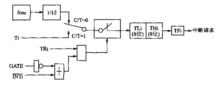
Figure 4.3 Structure diagram of T0 and T1 in mode 1
Way 3
When M0=0 and M1=1 in TMOD, it is 8-bit automatic reloading initial value counting or timing mode, and its structure is shown in Figure 4.4.
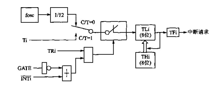
Figure 4.4 Structure diagram of T0 and T1 in mode 2
In mode 2, divide the 16-bit counter into two 8-bit counters, and THi is used to store the initial value. When the counter overflows, on the one hand, TFi is set to 1 to apply for interruption; on the other hand, the value of THi is automatically loaded into TLi.
Way 4
When T0 is mode 3, T1 is used as a baud rate generator, and its TF1 and TR1 resources are lent to T0 for use, and T0 can form two independent structures, in which TL0 forms a complete 8-bit timer/counter, and TH0 It is a timer that can only divide the crystal frequency by 12. Its structure is shown in Figure 4.5. When T1 is used as a baud rate generator, it can be set to mode 0, 1 or 2, which can be used in any occasion that does not require interrupt control. Generally, when T1 is used as a baud rate generator, it is often set to the automatic reinstallation mode of mode 2, and its structure is shown in Figure 4.6.
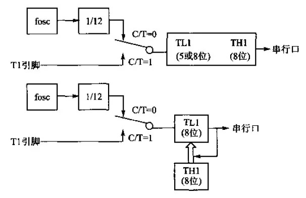
Figure 4.5 Structure diagram of T0 in mode 3
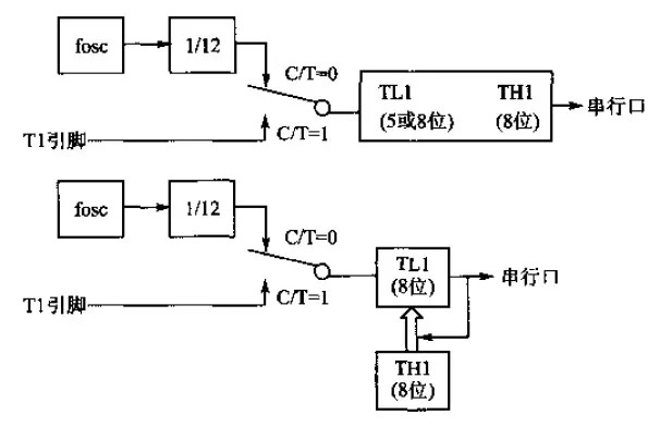
Figure 4.6 When T0 is mode 3, T1 is the baud rate generator
Shenzhen MovingComm Technology Co., Ltd. , https://www.movingcommiot.com