A wireless digital audio broadcasting system is a device that transmits a broadcast by means of wireless transmission. In general, shopping malls, campuses, or crowded public places use more. This article will show you how to make a wireless digital audio broadcasting system using a DVD or a computer. The method is relatively simple, just pay attention to the design and layout of the peripheral circuit.
The core components of this system are modular in design, and it is quite convenient and simple to pay attention to the peripheral circuit design and device position layout.
First, the principle of wireless digital audio transceiver module:The transmitting module is shown in the figure below. When the ordinary stereo audio times L and R are input, it is first processed by the analog-to-digital converter (ND) to generate a 44.1K/l6bit data stream, and then the data stream is sent to the digital signal processing. The processor (DSP) processes it and finally modulates it by a GFSK modulator of a 2.4 GHz phase-locked loop (PLL). The RF signal is amplified and sent out from the antenna.

The receiving module principle is shown in the figure below. The received signal is first amplified by a low noise amplifier (LNA), then into a 2.4 GHz phase-locked loop (PLL) GFSK demodulator for demodulation, and the demodulated data is entered. The digital signal processor (DSP) processes, processes the 44.1K/l6bit data stream, and then converts the data into an audio signal through a digital-to-analog converter (D/A).


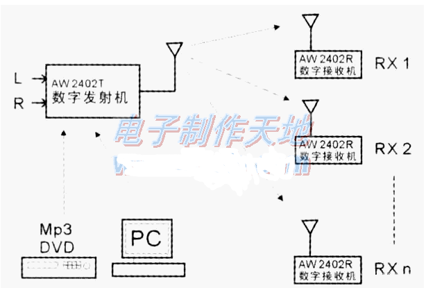
As shown in the above figure, high-fidelity audio broadcasting can be performed on countless receivers by connecting the transmitter to the source of the DVD or computer and setting the frequency.
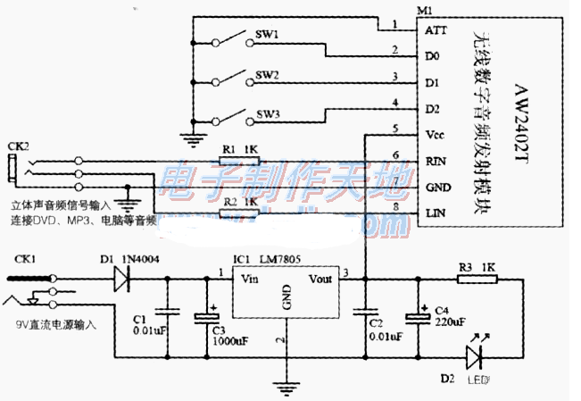
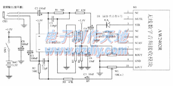
When the transmitter is designed according to the middle figure, the AW2402T module is laid out vertically, so that the built-in antenna is not affected by peripheral components. SWI, SW2, and SW3 can use code switches, and three switch state combinations can set eight groups of frequencies. When the receiver is designed as shown below, the 3.3V battery can be replaced by a mobile phone battery, which is durable and easy to purchase. The W1 is a double potentiometer to control the volume.
Pay attention to the installation, first do not install the module, after installing the peripheral components, test the transmitter regulated power supply, determine the voltage is 5V, then install the transmitter module. The receiver also needs to detect whether the polarity of the power supply is correct, whether the power amplifier circuit is working properly, and then install the module.

After all the installation is complete, turn on the receiver power supply SW1, the receiver status indicator flashes, then connect the transmitter audio source, power supply, and power indicator housing. At this time, the status indicator of the receiver changes from blinking to normal housing. There is a melodious musical sound. If several transmitters are working at the same time, just press SW2 to switch channels.

Energy Efficiency Management Solutions
Energy Efficiency Management Solutions,IoT Energy Magagement System,Hospital Isolated Power Sypply System,Solar PV Power Monitoring Solution,Data Center Presision Distribution Monitoring Solution,Wireless Temperature Monitoring Solution
Jiangsu Acrel Electrical Manufacturing Co., LTD. , https://www.acrel.com.pk