An analog-to-digital converter, or A/D converter, or ADC for short, usually refers to an electronic component that converts an analog signal into a digital signal. A typical analog to digital converter is a digital signal that converts an input voltage signal into an output. Since the digital signal itself does not have practical meaning, it only represents a relative size. It is widely used in signal acquisition and processing, communication, automatic detection and multimedia technology. This article describes the test methods for AD static parameters and dynamic parameters.
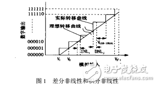
Definition of static parameters of performance parameters of analog-to-digital converterFigure 1. Differential nonlinear DNL is defined as the difference between the step voltage of the actual transfer and the ideal step.

Where N is the number of converter bits, D is the digital code output by the converter, VD is the minimum input voltage corresponding to the output digital code D, and VLSB-IDEAL is the minimum input voltage that ideally changes the output of AD by one bit. Usually the maximum value in (1) is defined as the differential nonlinearity error of the entire analog-to-digital converter, namely:


Integral nonlinear INL: defined as the deviation of the actual transfer curve of the analog-to-digital converter from the ideal transfer curve. The formula is expressed as:

Disorder:

Gain error: defined as the deviation of V2N-1 from the ideal value,

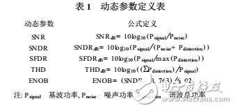
The dynamic parameters of the analog-to-digital converter are defined as shown in Table 1.

Analog to digital conversion of the static tests are generally two ways - ramp voltage tests and code density test [2-4] (histogram test).
The ramp voltage test is to add a slowly ramping wave at the input of the AD, directly record the transfer characteristic curve of AD, and then calculate the static parameters of AD by using equations (1) to (6). This is a relatively traditional solution, the advantage is that the principle is simple, but there are some shortcomings:
(1) Introducing other errors. Since the ramping ramp is generated by a digital voltmeter (DVM), although the digital voltmeter can be very precise and the noise is small, the DAC error is introduced into the circuit, so the ADC above 16 bits rarely Test with this method.
(2) Limited precision. The accuracy of the DVM and the digital voltmeter that measures the ADC input corner voltage limits the accuracy of the test protocol.
(3) Low efficiency. Since it is necessary to measure the input voltage corresponding to each digital code in turn, it takes a long time to measure one AD, so this scheme is only suitable for testing small-scale and medium-precision ADCs.
The code density test is to add a low-frequency sinusoidal signal slightly larger than the AD input range at the input end of the AD, collect the output data, and count the number of occurrences of each digital code N(i), and obtain the transfer curve of AD by mathematical calculation, that is, Digital output code i corresponding to the input voltage

Finally, NL, DNL, ​​and the like are determined by substituting (7) into equations (1) to (6).
The program pays attention to the following points:
(1) The input signal amplitude is slightly larger than the AD input range. Because of the fact that there is an imbalance in the actual situation, only the input signal is greater than the full scale to ensure that all 0 and all 1 digital codes can appear, and can also reduce the main source of error - the error near the sinusoidal peak. Overdrive voltage meets:

Where: δ = root mean square of noise power, B = error tolerance.
(2) The frequency of the input signal is in a qualitative relationship with the sampling frequency of the data acquisition instrument, so as to conform to the random distribution of statistics.
(3) The total number of points sampled should satisfy the formula (9):

Where: Nt = number of sampling points, n = AD precision α = NL, DNL, ​​required accuracy 60
Because the code density test has high precision, high speed and easy instrument, this method is used to test the static characteristics.
Nantong Boxin Electronic Technology Co., Ltd. , https://www.ntbosen.com