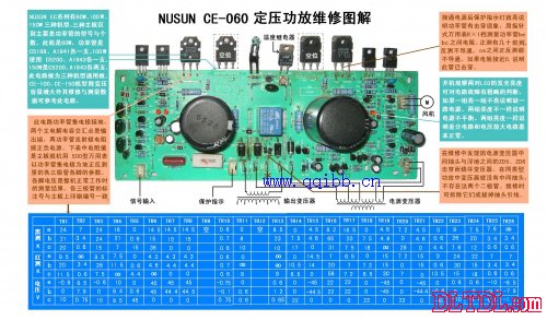
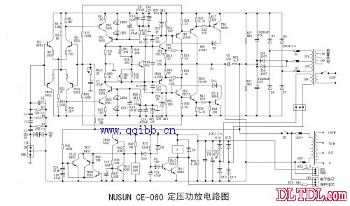
NUSUN CE-060 is one of Aipu's Lexon CE series products. The drawing is a schematic diagram of the main power amplifier circuit drawn according to the real object. The signal from the front circuit is input to the power amplifier board through the CN1 socket. The two docked 3V voltage regulators ZD1 and ZD2 limit the input signal peak to 3.6V to prevent over-excitation from damaging the main circuit. C1, C2, C3, R1, R2, R3, and C4 form a bandpass filter to filter out low frequency interference signals and ultra high frequency signals.
TR1, TR3 and TR24, TR23 form a dual differential input amplifier. Because the ZD4 and ZD7 regulator circuits provide ±12V stable voltage, the differential amplifier does not have a constant current source and a mirror current source. TR4, TR2, TR25, and TR26 form a 渥mann (co-impact-co-base) voltage amplifying circuit, which is commonly used in high-grade Hi-Fi power amplifiers. Because the single-tube common-emitter amplifier has a higher voltage gain, the Miller effect causes poor high-frequency characteristics of the amplifier. Although the single-tube common-base amplifier has good frequency characteristics, it has no voltage gain. Combining the two circuits in series into a cascode-co-base circuit greatly reduces the Miller effect by improving the impedance characteristics of the common-emitter circuit. The voltage amplification stage has good frequency characteristics and high voltage gain. LED1, LED2 and LED3, LED4 LEDs are TR2, TR26 base voltage regulator, which overcomes the noise generated by the regulator tube and diode switch state, because the LED is always in a stable conduction state during operation.
TR10 is a constant voltage biasing tube, and its base upper bias thermistor VR1 is bonded to the heat sink with thermal grease for temperature compensation. When the tube temperature and the heat sink temperature increase, the VR1 resistance decreases, increasing the TR10 bias and increasing the conduction, thereby reducing the voltage between the collector and the emitter. The bias of TR5 and TR22 is reduced, and the quiescent current is reduced, which plays the role of automatic gain control. In the general OCL circuit, the two tubes are current amplification stages, but the input into the emitter output in this circuit is changed to the collector output, so it becomes another level of voltage amplification. C5 and C21 are vibration absorbing capacitors for high frequency compensation to prevent self-excitation. TR7, TR21 are current amplification stages, also known as push stages. TR8 and TR15 are power output stages. The two parts of the tube are different from the general OCL circuit, and the collector output is used.
The output midpoint grounding (the whole circuit ground) is the biggest feature of this amplifying circuit, making the floating ground of the power supply a true output. In the general OCL power amplifier circuit, the double tap of the 33V winding of the power transformer is the grounding point of the whole machine, and the middle tap here can be used, including ZD5 and ZD6 can be completely removed. The double 33V winding is actually a single winding of 66V. The AC voltage of the AC is 66V, and the 90V DC voltage after rectification and filtering by D3, D5, D6 and D7 is divided by two main electrolytic capacitors and R27 and R31 to form a floating junction. The ±45 voltage of the ground supplies power to the power amplifier circuit.
The primary winding of the output transformer as a load is connected between the floating ground and the circuit ground. This way, tubes of different polarity can be mounted directly on the same heat sink without the mica plate, simplifying the installation. The floating output is similar to the OTL circuit. The output transformer is loaded by two main electrolytic capacitors, which avoids the DC current flowing through the output transformer when the circuit fails, effectively preventing the output transformer from being damaged. It is the special output mode of the end that causes the output of the front differential amplifier to be output from the collector of the inverting input transistors TR1 and TR24. The negative feedback signal is changed from the output midpoint to floating. TR6 and TR19 are overcurrent protection tubes. When the current of the power tube is too large, the voltage drop of the emitter resistors R21 and R38 will increase. The sampling voltage will make the two tubes conduct, and D2 and D11 will be used to shunt the base of the push tube. , to reduce the output current of the power tube. C8 and R22 form a Jubel compensation network to compensate the phase shift caused by the pure inductance of the output transformer winding to the high frequency signal and overcome the high frequency self-excitation.

TR18, TR20, and TR17 form a protection detection circuit, and the floating output signal passes through R41 to the detection circuit. The AC component is filtered out by C20 and C19. If the output terminal has a positive voltage TR18, it will be turned on, and a negative voltage TR20 will be turned on. After TR20 is turned on, TR17 is turned on, and TR18 is also turned on, and the collector voltage is grounded. When the three tubes are turned on, the reset phenomenon occurs due to loss of power supply, and the addition of TR14 and TR16 functions to prevent the reset from occurring.
After the current three tubes are turned on, the base of TR16 is turned on by R40 to be turned on. Its collector output high level turns TR14 on, and this turn-on is not automatically reset. It can only be restored if the power is turned off. After the whole machine is turned on, the five tubes are in the off state, and the 18V AC voltage of the power transformer is rectified and filtered to supply 24V DC to the fan and the protection circuit. The 24V voltage is charged to C14 via R33. Because R33 has a large resistance value, the process of charging to 12V is the time when the load is delayed. When the voltage at the upper end of C14 exceeds 12V, D12 breaks through and turns on. TR13 and TR11 quickly saturate and conduct, and the relay pulls on and closes the load.
When the five tubes are turned on before the floating output has DC output, the voltage on C14 will be close to 0V after D10. TR13, TR11 are cut off, the relay is released, and the load is disconnected. The 67F090 is a normally open temperature relay that is fixed on the heat sink. When the tube temperature is too high and the heat sink temperature reaches 90°, the relay will close and the protection relay will be released. The CN2 is a signal output socket that is sent to the display panel level indication and protection indication. The power transformer dual 18V is the power supply for the front and control circuits. In addition to the three constant voltage output terminals, the output transformer has a multi-way selector switch and an output terminal.
Creative Led Display,Creative Led Screen,Creative Stage Led Display,Platform Creative Led Display
ShenZhen Megagem Tech Co.,Ltd , https://www.megleddisplay.com