A few days ago, my good friends shared some pictures with the editor, and the editor saw the urge to hit the wall.
I believe that the engineers who see these pictures will have a lot of bitter and helpless scenes in their minds instantly:
A: There is a problem with your product design. You see that the throughput value is sometimes high and sometimes low, and the difference is huge... .
B: In the same office, I used my mobile phone to test that the Wi-Fi throughput value is higher than yours in the same location...
C: I compared the Wi-Fi throughput of your product and competing products in the office... .
D: There is a problem with the wireless screen transfer function of your product. I will experience freezing when I transfer images and videos in the office...
E: I used my mobile phone to connect your product to test the Wi-Fi throughput in the office. I turned the mobile phone 90 degrees and the throughput value dropped by half. There is a problem with the stability of your product... .
F: I want to test the Wi-Fi throughput in an actual application environment like an office, and see how your product’s Wi-Fi throughput and anti-interference ability are in the actual environment...
Do you also experience the despair that the editor has experienced before? But the editor's heart is thinking of everyone~ As a sage stepping on the pit, Ban Mei decided to share with you a wave of tips for getting around the pit~~

Knocking on the blackboard: today's focus
1. What is the theoretical rate of Wi-Fi?
2. What is the basis for these theoretical rates?
3. How is the theoretical rate of Wi-Fi calculated?
4. Why can the theoretical rate of Wi-Fi keep changing?
V. Shannon's theorem and Wi-Fi theoretical rate
Sixth, the basic principles of Wi-Fi radio frequency applications
Seven, Wi-Fi radio frequency interference
8. Summary
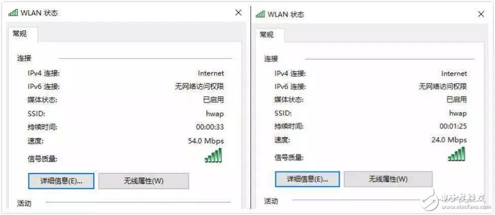
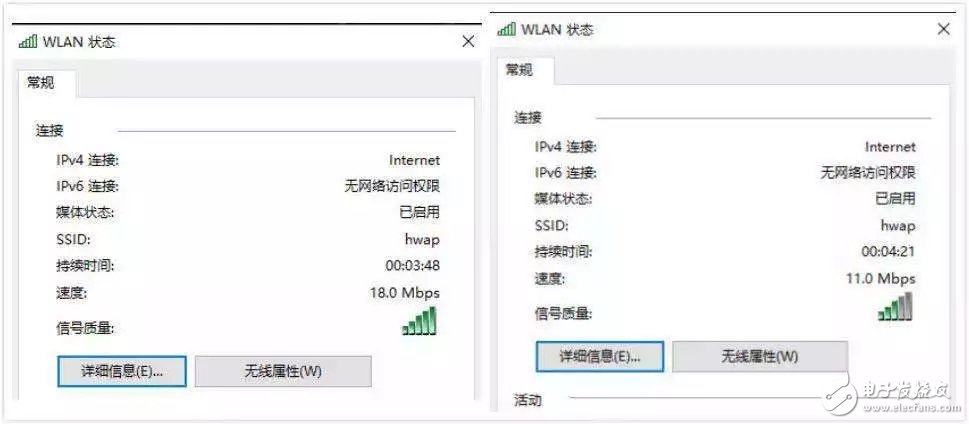
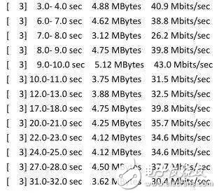
The "speed" in the picture posted by Jiyou is the theoretical rate of Wi-Fi read through the computer network card. (Which Wi-Fi protocol is the theoretical rate, you guys can guess for yourself)
The theoretical rate of Wi-Fi is calculated based on information such as different modulation methods, code rates, the number of coded bytes carried by a single subcarrier, the total number of subcarriers carrying data, the number of spatial streams, and the time spent in a single Wi-Fi data transmission. from.
Of course there is a basis!
Please take a look at some of the theoretical rates listed in the IEEE 802.11g (Figure 1) and IEEE 802.11n (Figure 2, Figure 3, and Figure 4) protocols below:
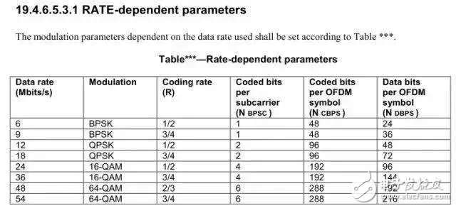
(Figure 1: IEEE 802.11g theoretical rate set)
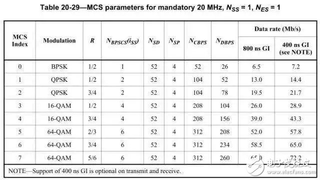
(Figure 2: IEEE 802.11n-HT20 1T/R theoretical rate set)
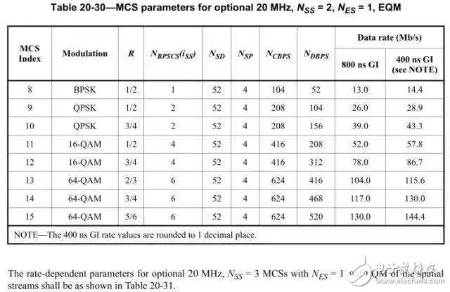
(Figure 3: IEEE 802.11n-HT20 2T/R theoretical rate set)
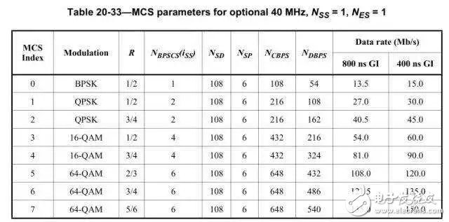
(Figure 4: IEEE 802.11n-HT40 1T/R theoretical rate set)
For example, how is the theoretical rate calculated in this mode of 802.11n-HT20-MCS7: (In addition, the 802.11n protocol supports 2.4G and 5.8G dual frequency)
1. The time for each Wi-Fi data transmission is 4μs (this point is the same for all Wi-Fi protocols);
2. MCS7 uses 64-QAM modulation technology (refer to the above figure), which means that each subcarrier can transmit 6bit (2 to the 6th power = 64) data at a time. When the rate is MCS7, its corresponding code rate (Coding rate) is 5/6;
3. In HT20, OFDM divides the 20M bandwidth into 56 subcarriers, and the number of subcarriers used for data transmission is 52; (refer to Figure 2 for MCS7, Nsd=52, Nsd: Number of complex data numbers per spatial stream per OFDM symbol )
4. So in MCS7 of HT20, the rate = (1/4us)*(52*6bit)*5/6 = 65Mbit/s, and when there are multiple spatial streams, multiply by the spatial streams working at the same time (the number of antennas ) Yes, the installed fake antenna is not counted. The calculation method for other rates is the same.
Note: Wi-Fi single data transmission time 4μs is the same for all modes, please refer to the following calculation:
4μs=Ndbps/DR; Ndbps= Number of data bits per OFDM symbol is the data bit rate transmitted by each OFDM symbol (refer to Figure 1, 2, 3, 4), DR=Data Rate; for 802.11g-54Mbps , Transmission time=(Ndbps=216)/54Mbps=4μs; for 802.11n-HT40-MCS7 1T/R, transmission time=(Ndbps=540)/135Mbps=4μs
The theoretical rate of Wi-Fi actually reflects the current changes in air interface channel quality.
When transmitting, Wi-Fi data packets usually initiate transmission (negotiation) on the air channel at the highest coding efficiency protocol rate supported by the device at the beginning, but at this time, the current channel is due to factors such as signal strength, distance, interference, etc. When large delays and errors occur in data transmission, in order to more effectively suppress the delay and error of data transmission, the 802.11 series Wi-Fi protocol stipulates that the Wi-Fi equipment at this time needs to adopt the correct The channel environment requires relatively low modulation and coding methods to improve the ability of data messages to resist errors and delays in the air interface.
For example, in the picture sent by the base friend, the rate was adjusted from 64-QAM (54Mbps) to CCK (12Mbps) in a short time, but while improving the error resistance ability, the data coding efficiency was sacrificed. This is reflected in this time The decrease of the air interface protocol rate means the decrease of the theoretical rate, which is the Wi-Fi rate reduction that everyone often calls.
In the office environment, because the Wi-Fi channel environment is constantly changing, in extreme cases, it may even be connected and disconnected from time to time. The theoretical rate has also been changing, and the measured throughput data will also be constantly changing. Dynamic changes.

In the last century, Mr. Shannon put forward the theorem based on ideal Gaussian white noise interference channel capacity, signal-to-noise ratio, and capacity (the following formula). Unlike the Nyquist theorem, the channel model it chooses has noise interference. , Which is closer to the actual communication data exchange.
C=B log2(1+S/N)
C is the channel capacity, B is the bandwidth, and S/N is the signal-to-noise ratio. (The noun formula is boring, but the tree of theory is evergreen)
Among them, the channel capacity C can be understood as the maximum theoretical transmission rate of the used channel under different B and S/N states. Combined with Wi-Fi 802.11 protocols, such as 802.11b, which has a 20MHz bandwidth (actually 22MHz) within a specific S/N range (this value is related to chip performance), its C value can be characterized as 11Mbps, and the one used at this time The modulation method is CCK; in the same way, when the value of 802.11n-HT20 -MCS7 1T/R, its C value can be characterized as 65Mbps (if GI=400ns is supported, it is 72.2Mbps)
For Wi-Fi throughput testing, after bandwidth B is determined, its theoretical rate is positively correlated with the signal-to-noise ratio. The higher the signal-to-noise ratio, the greater the theoretical rate; in other words, the signal-to-noise ratio becomes the current Wi-Fi channel communication environment and communication quality are important evaluation indicators, which reflect the quality of the current air interface channel. It is also an important basis for the algorithm adjustment and switching of the aforementioned code rate, modulation and demodulation, and encoding methods. The current channel When the change of the signal-to-noise ratio exceeds a certain threshold, the theoretical rate and modulation method of Wi-Fi will be adaptively switched.
In fact, for some relatively professional wireless terminal manufacturers, even in a professional testing throughput laboratory, they will read the S/N and Noise values ​​in the current test environment from the chip side as a reference basis for testing.
In the process of using Wi-Fi in the office (home or public places), there are often phenomena such as slow network speed, long network delay, and disconnection. The reasons for this phenomenon include poor signal coverage and load on Wi-Fi terminal equipment. Excessive weight (caused by poor data processing capabilities of the product), a more common factor is radio frequency interference.
However, the radio frequency interference of Wi-Fi is in addition to the common coexistence interference of other wireless systems to Wi-Fi, the adjacent channel interference of Wi-Fi terminals, and the interference on the physical layer of Wi-Fi radio frequency (such as the power supply of the product itself, DDR and other interference to Wi-Fi), there is also such a situation:
When a large number of Wi-Fi terminals share the same air interface channel for continuous large-volume data transmission (such as playing high-definition video), the probability of data frame collisions in the channel will increase, and the frequency of data frame retransmission will increase, resulting in the current channel The signal-to-noise ratio becomes worse, and the transmission time of a single data frame becomes longer. In the end, you can only maintain basic communication by reducing the transmission efficiency and rate of the air interface channel (of course, this will not happen in a professional testing throughput laboratory) . When the air interface load increases to a certain level, slow network speed, packet loss, and even dropped connections will occur that affect the user experience.
So how did this happen? The energy ahead is high again!
1) Time slot collision, network delay and packet loss
As everyone knows, the air interface channel of Wi-Fi is a TDD (Time Division Duplex) time division system. A basic data frame operation is composed of multiple frame structures, and the frames are distinguished by "interframe spacing". When accessing 802.11 media, the distributed inter-frame space (DIFS) is usually used as the starting point to start the entire frame exchange sequence, and the subsequent frames are distinguished by the short inter-frame space (SIFS). A basic data frame transmission process is shown in Figure 5.
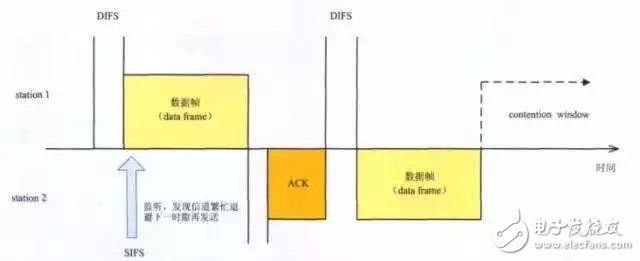
Figure 5
As shown in the figure above, when staTIon 1 transmits data in a certain time slot, staTIon 2 initiates a request to monitor the channel. At this time, because the channel is already occupied, staTIon2 can only wait to avoid a random time slot, and then monitor the channel again, until the channel is free and lasts for a DIFS time before it can transmit the relevant data frame, and then wait for ACK, ACK Feedback after a SIFS time.
When the channel is frequently used, multiple staTIon monitors that the channel is idle and sends data at the same time, and then there is a collision in the time slot, which causes the data transmission to be unsuccessful and no ACK (acknowledgement frame) is returned, so it retransmits again. The network delay becomes larger due to retransmission.
Generally, the retransmission setting for long frames is set to 7 times, that is, when the data frame is backed off and retransmitted 7 times and there is no ACK response, the data frame is discarded. At this time, for network applications, there will be bit errors and packet loss. .
This is the Wi-Fi carrier monitoring and collision avoidance mechanism.
2) Delay and bit errors lead to lower-order modulation
When due to factors such as signal strength, distance, interference, etc., large delays, errors and even packet loss occur in data transmission, in order to more effectively alleviate delays and errors, and ensure the accuracy of data transmission, The 802.11 protocol stipulates that Wi-Fi terminal devices need to adopt lower-level coding methods (such as base friends, adjusted from 64QAM 54Mbps to CCK 11Mbps) to improve the ability of data packets to resist errors and delays in the air interface. The advantage of this mechanism is that it can improve the ability to resist errors, but the disadvantage is that it reduces the coding efficiency.
Specifically for AP/STA devices, when there are more delays, bit errors, packet loss, etc., they will think that the quality of the air interface channel has deteriorated, so according to the channel environment, they adopt a coding method with strong anti-interference ability. For data transmission, the lower the encoding method, the lower the encoding efficiency and the larger the occupied time slot of the data frame. In the end, this method causes the time slot of each data frame to gradually increase.
The decrease in the theoretical rate of the air interface channel leads to an increase in the length of each data frame (a single Wi-Fi data transmission time is 4 μs), which further intensifies the conflict competition on the air interface channel; when the competition intensifies to a certain extent, it forces all terminals The coding method with stronger error resistance capability, that is, the lower-order modulation method, is used to ensure the quality of data transmission, thus entering a vicious circle like dominoes.
3) Low-level modulation means lower number of bits per symbol
In the 802.11 protocol, the high-rate wireless data access capability mainly comes from its multi-carrier modulation technology OFDM (Orthogonal Frequency Division Multiplexing Modulation). OFDM uses n-QAM, where n represents the modulus of various modulations mapped onto the constellation diagram. Since the points on the constellation diagram need to be accurately positioned to achieve correct demodulation, the lower the modulus, the lower the modulation mode, the lower the requirements for signal transmission conditions, and the better it is to adapt to harsh conditions. Air interface transmission environment.
However, by adjusting the coding method, while improving the anti-interference ability, the number of bits per symbol is reduced, and then the theoretical transmission rate is also reduced accordingly. (Figure 6: 64-QAM and 256QAM constellation diagram; Figure 7: 256QAM constellation diagram in the first quadrant).
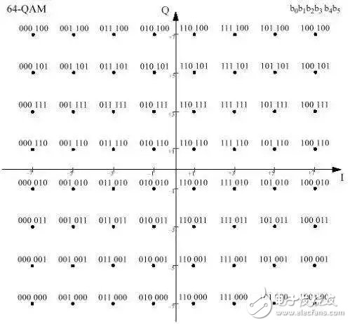
Figure 6
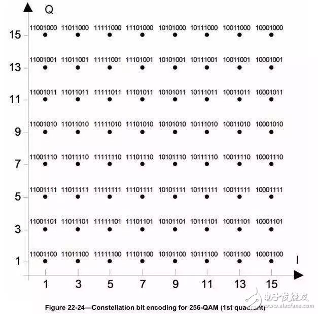
Figure 7
As mentioned in the sixth part, Wi-Fi radio frequency interference includes: coexistence interference of other wireless systems to Wi-Fi, adjacent channel interference of Wi-Fi terminals, interference received on the Wi-Fi radio frequency physical layer, and Wi-Fi Fi carrier sense and co-channel interference caused by collision avoidance mechanism.
The following data are two typical Wi-Fi radio frequency interference data for reference:
1) Comparison data of Wi-Fi Bluetooth coexistence interference throughput
Figure 8 shows the data of Wi-Fi connection only in the throughput laboratory. Figure 9 shows the data of the Bluetooth speaker connected to the Bluetooth speaker when the Wi-Fi throughput is tested. The test mode is 802.11n-HT20.
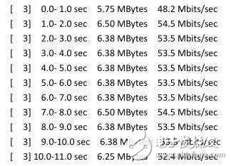
Figure 8
Picture 9
2) Interference of microwave oven to Wi-Fi
Figure 10 shows the changes in Wi-Fi throughput data when the microwave oven is turned on and off when testing the notebook Wi-Fi throughput in a home environment.
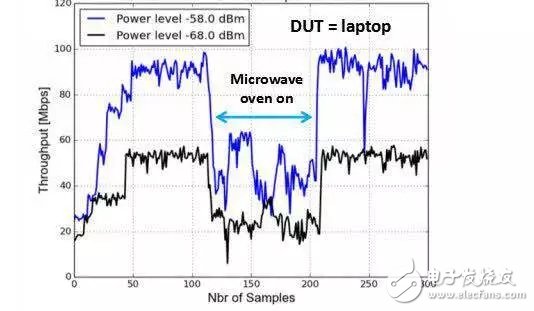
Picture 10
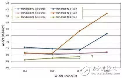
3) Interference of 4G signal to Wi-Fi
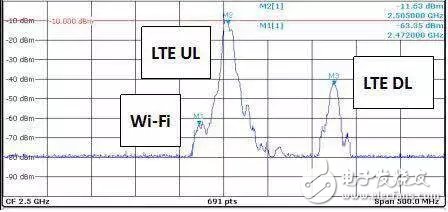
Figure 11 shows the impact of connecting and closing LTE Band 7 (UL = 2 505 MHz) on the TIS data of different 2.4G Wi-Fi channels when different handheld devices test Wi-Fi OTA TIS. Figure 12 shows the spectrum when the device turns on LTE Band 7 (UL = 2 505 MHz) and works on Wi-Fi ch13.
Picture 11
Picture 12
The actual transmission environment of offices and homes is more complicated. In addition to the coexistence interference of various wireless systems and the possible interference on the Wi-Fi radio frequency physical layer, there are also Wi-Fi's own carrier monitoring and conflict avoidance mechanisms that cause air interface channel congestion, The self-interference of the theoretical rate reduction is caused by the communication mechanism of Wi-Fi itself. As long as Wi-Fi is used in the actual environment, it cannot be avoided.
The above situations are the reasons why it is impossible to quantitatively evaluate the wireless performance stability of Wi-Fi products and the anti-interference ability of Wi-Fi products in the actual environment through the Wi-Fi throughput test in the actual environment. Testing Wi-Fi throughput to quantify and evaluate the RF anti-interference ability of a product is itself a false proposition.
PVC keychain maker,pvc keychain manufacturers,pvc figural keychain,pvc keychain handmade,pvc keychain online
Shenzhen Konchang Electronic Technology Co.,Ltd , https://www.konchangs.com