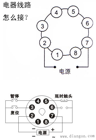
Wiring plug: 8-pin round plug pin definition:
Wiring method 1 (domestic regular) Wiring method 2 (OMRON)
Needle number definition
1 Relay B common 1 external switch common
2 power supply line N (AC85-265V)
3 Relay B normally open contact 3 time reset terminal (RESET) / switch on effective
4 Relay B normally closed contact 4 timing enable terminal (GATE) / open effective
5 Relay A normally closed contact 5 Relay A normally closed contact
6 Relay A normally open contact 6 relay A normally open contact
7 power line L (AC85-265V)
8 Relay A common 8 Relay A common terminal How to wire this time relay?

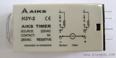
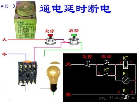
13,14 After the power is connected, the relay is energized. After the set time, another indicator light is also on, but after the 5 and 8 are connected to the device, the device is not powered. The device can be connected to 9-5 or 12-8. For example, if you want to delay the lighting of a light bulb, you should connect the zero wire directly to the light bulb, connect the fire wire to the 9 or 12 terminal, and connect the 5 or 8 to the light bulb.
13, 14 feet are connected to DC power supply, 13 feet are negative, 14 feet are positive.
1-9, 4-12 are normally closed contacts,
After the power is turned on, the set time is reached, 1-9 is turned off, 5-9 is turned on, 4-12 is turned off, and 8-12 is turned on.
After the power is turned off, 1-9 is immediately turned on, 5-9 is turned off; 4-12 is turned on, and 8-12 is turned off.
13.14 is the coil, connected to the power supply. 1-9, 4-12 is a normally closed contact.
After the power is turned on, the relay starts timing, reaches the set time, the relay operates, 1-9 is disconnected, and 5-9 is turned on. The opposite is also the same.
After the power is turned off, the relay is reset, the time is 0, 1-9 is turned back on, and 5-9 is turned off.
This kind of relay is made in Hong Kong. 4-12 and 1-9 are normally closed contacts, and 8-12 and 5-9 are normally open contacts. 13-14 is the coil working power supply, connect the coil, pay attention to the rated current of the contact is 5A, the load current can not exceed 5A when used, otherwise the contact will be burnt.
DH48S-S time relay wiring method


Product model: DH48S-1Z

Wiring method of time relay First, control wiring: You consider it as a DC relay. 3, 7 is used to connect 12V control voltage; 2, 7 is used to connect 24V control voltage. Among them, 7 is regarded as the negative pole of direct current, and is connected to the neutral line when in use. 2 connected to the 220V fire line.
Second, work control: Although the control voltage is connected, but whether it plays a control role, it is determined by the timer on the panel.
Third, the function understanding: it is a switch, single-pole double-throw, has a movable point movable arm, just like the movable blade arm of the common knife switch. 8 is the active point, 5 is the normally closed point, when the relay does not move, they are connected. When moving, 8 and 6 are connected.
Fourth: Load wiring: the neutral or negative terminal of the power supply is connected to the neutral or negative terminal of the appliance. The live wire of the power supply or the positive pole is connected to the 8th pin, and the live wire end of the electric appliance or the positive pole is connected to the 6th pin, and the 5th leg is idle.
Fifth, the working principle: during the period of invalid timing, 8 and 5 are connected, which is equivalent to the disconnection of our normal light switch. When it is effective, the relay acts, 8 and 6 are connected, and the electrician works well. It is equivalent to our normal light switch on state. Wiring plug: 8-pin round plug pin definition:
Wiring method 1 (domestic regular) Wiring method 2 (OMRON)
Needle number definition
1 Relay B common 1 external switch common
2 power supply line N (AC85-265V)
3 Relay B normally open contact 3 time reset terminal (RESET) / switch on effective
4 Relay B normally closed contact 4 timing enable terminal (GATE) / open effective
5 Relay A normally closed contact 5 Relay A normally closed contact
6 Relay A normally open contact 6 relay A normally open contact
7 power line L (AC85-265V)
8 Relay A common terminal 8 Relay A common terminal

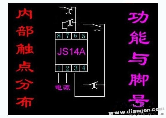
1, 2 is the power supply, the first group 3, 4 is normally open, 3, 5 is normally closed,, the second group 6, 7 is normally open, 68 is normally closed
Incremental Encoder is commonly used, and Absolute Encoder is used if there are strict requirements on position and zero position. Servo system should be analyzed in detail, depending on the application situation. Commonly used incremental encoder for speed measurement, which can be used for infinite accumulation measurement; Absolute encoder is used for position measurement, and the position is unique (single or multiple turns). Finally, it depends on the application situation and the purpose and requirements to be realized.
Incremental Linear Encoders,Linear Optical Encoder,Linear Position Encoder,Encoder Bearing Tester
Yuheng Optics Co., Ltd.(Changchun) , https://www.yhenoptics.com