Electrocardiography (ECG) is a science that converts cardiac ionic depolarization (ionic depolarizaTIon) into measurable electrical signals for analysis. One of the most common challenges in analog electronic interface to electrode / patient design is optimizing the right leg drive (RLD), which aims to achieve higher common mode performance and stability. Using SPICE analysis can greatly simplify this design process.
In the ECG front end, the RLD amplifier has a common-mode electrode bias of Vref, and feeds back the common-mode noise signal (enoise_cm) after inversion processing to reduce the total noise at the input of the gain stage of the measurement amplifier. In Figure 1, the source ECGp and ECGn are separated to show how the RLD amplifier provides a common-mode reference point for a portion of the ECG signal, and this portion of the ECG signal can be seen at the positive and negative input terminals of the measurement amplifier (INA). The parallel RC combination of the left arm, right arm, and right leg represents the lumped passive electrode connection impedance (expressed later in this article by 52kΩ and 47nf). Assuming that enoise is coupled to the input in a parasitic manner, the feedback of enoise_cm will reduce the total noise signal at each input and use an external method to filter the residual noise or use the common-mode rejection ratio (CMRR) of the measurement amplifier to suppress it.
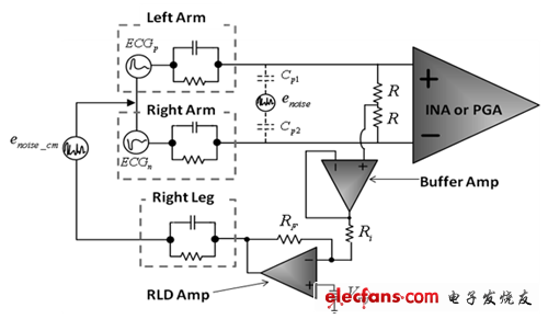
Figure 1 LEAD I and RLD simple connection
In Figures 2, 3, and 4, we can see changes in common-mode rejection, indicating that the common-mode test circuit has different RLD amplifier gains. These figures show that the best low-frequency CMRR is achieved without feedback resistors (that is, infinite gain); however, in the real world, for applications that require the RLD amplifier to operate linearly after an input amplifier lead is unplugged It may not be practical to remove the DC path and / or set RF to a certain high value.
Figure 2 Relationship between CMRR and RLD gain
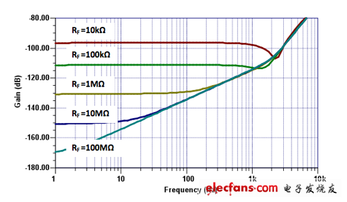
Figure 3 Relationship between CMRR graph and frequency and RLD gain (RF)
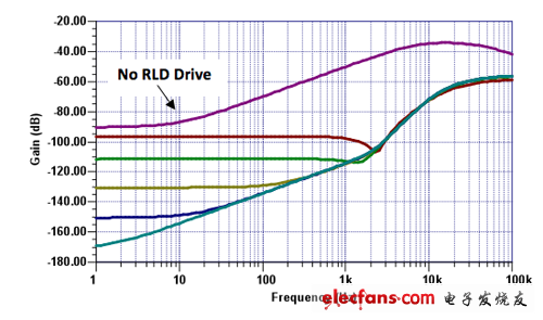
Figure 4 Relationship between MCRR RLD and no RLD
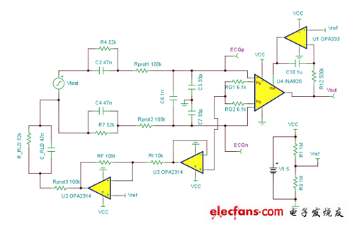
Figure 5 small signal pulse test circuit
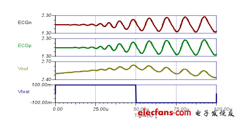
Figure 6 Figure 5 The output curve
Photovoltaic New Energy Magnetic Ring Inductor
Photovoltaic New Energy Magnetic Ring Inductor,Common Mode Toroidal Inductors,High Frequency High Power Inductors,Three-Phase Common Mode Filter Inductor
Shenzhen Sichuangge Magneto-electric Co. , Ltd , https://www.rodinductor.com