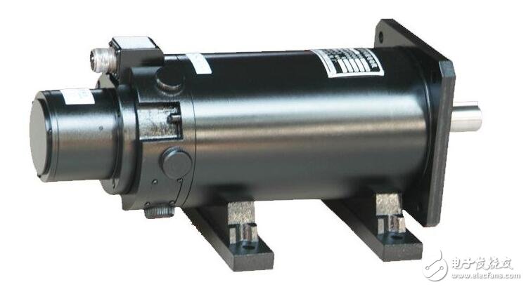
DC servo motor, which comprises a stator, a rotor core, a motor shaft, a servo motor winding commutator, a servo motor winding, a speed measuring motor winding, a speed measuring motor commutator, and the rotor core is stacked and fixed by a steel sheet It is formed on the motor shaft. The servo is mainly positioned by pulse. It can be basically understood that when the servo motor receives one pulse, it will rotate the angle corresponding to one pulse to realize the displacement. Because the servo motor itself has the function of emitting pulses, the servo motor has every When an angle is rotated, a corresponding number of pulses are emitted, so that the pulse received by the servo motor forms an echo, or a closed loop, so that the system knows how many pulses are sent to the servo motor, and how many pulses are received at the same time. In this way, the rotation of the motor can be controlled very accurately, so that accurate positioning can be achieved, which can reach 0.001 mm.
DC servo motor refers to DC brushed servo motor - high motor cost, complex structure, large starting torque, wide speed range, easy control, maintenance, but inconvenient maintenance (replacement of carbon brushes), electromagnetic interference will occur. The environment is required. Therefore it cannot be used in general industrial and civilian applications that are cost sensitive.
The DC servo motor also includes a DC brushless servo motor—the motor is small in size, light in weight, large in output, fast in response, high in speed, small in inertia, smooth in rotation, stable in torque, and limited in motor power. It is easy to realize intelligence, and its electronic commutation mode is flexible, and it can be commutated by square wave or sine wave. Motor maintenance-free, there is no carbon brush loss, high efficiency, low operating temperature, low noise, small electromagnetic radiation, long life, and can be used in various environments.
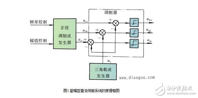
1. Position detection and signal integration
(1) Revolving transformer: It is an angular displacement measuring device whose output voltage varies with the rotation angle.
(2) Phase-sensitive amplifier: converts the AC voltage into a DC voltage proportional to it and adapts its polarity to the phase of the input AC voltage.
(3) Position detection and signal integration
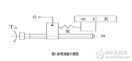
2. Pulse width modulation (PWM) power amplification
Basic principle: Using the switching function of high-power electrical appliances, the DC voltage is converted into a square wave voltage of a certain frequency, and the average value of the output voltage is changed by the control of the pulse width of the other side.
(1) PWM converter

(2) Bipolar PWM converter
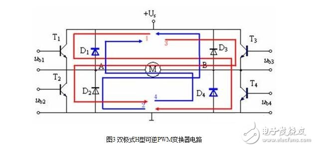
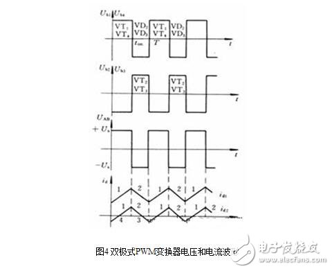
According to the figure, it is easy to derive the expression of the average voltage across the armature of the bipolar reversible PWM converter.

Bipolar PWM converter features:
advantage:
1 current continuous;
2 allows the motor to operate in four quadrants;
3 When the motor is stopped, there is a micro-vibration current, which can eliminate the friction dead zone;
4 At low speeds, the drive pulse of each transistor is still wide, and a transistor is reliably turned on;
5 Good stability at low speed and wide speed range.
Disadvantages:
During the working process, the four power transistors are in the switching state, the switching loss is large, and the accident of the upper and lower tubes is easy to occur. In order to prevent the upper and lower tubes from being turned on at the same time, a logic delay should be set between the driving pulse of one tube being turned off and the other tube being turned on.
Steady-state error analysis of DC servo system
The factors affecting the steady-state accuracy of the servo system and causing the steady-state error of the system are as follows: detection error caused by the detection component; principle error caused by the structure of the system and the input signal; disturbance error caused by the load disturbance.
1. Detection error
2. Principle error
3. Disturbance error
Dynamic correction of DC servo system
method:
1. The design of the speed regulator.
2, the design of the position regulator.
The composition and control of DC servo systemDC servo is similar to AC servo, and can be controlled by controller open loop control, controller semi-closed loop control and full closed loop control system.
The structure of the DC servo system control panel is as follows: the right side of the panel is the interface with the DC servo motor interface board, including the motor drive interface and the encoder interface; the left side is the interface with the motion controller panel, including the position control mode interface and the speed control mode. interface.
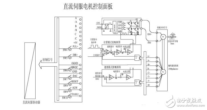
The M+, M-signal is the power line for the DC brushless servo motor and is used to drive the motion of the motor.
The A+, A-, B+, B-, C+, C-, 5+, 0V signals are encoder signals that are used to feed back the actual position of the motor shaft.
A, /A, B, /B, C, /C, +5V, PUL+, DIR+, OGND, OVCC, GND, DAC, RESET, ALM, ENABLE are control signals connected to the controller.
Its meaning is:
A, /A, B, /B, C, /C are the encoder signals that the driver feeds back to the motion controller.
+5V is the power supply.
PUL+, PUL- is a pulse signal for motor control in position mode.
DIR+, DIR- is the direction signal for motor control in position mode.
OGND, OVCC, and GND are analog ground, analog power and digital ground.
The DAC is the analog control signal that the driver accepts, typically ranging from -10V to 10V.
RESET, ALM, and ENABLE are control signals that indicate the reset, alarm, and enable functions of the drive.
DC servo drives typically have a speed control mode and a position control mode.
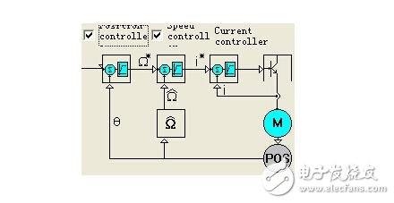
When using the position mode, the input control signal is pulse and direction (either positive and negative pulse). When using the speed mode, the input control signal is analog. The driver converts the input signal into a speed control signal, which is converted into a current control signal by a speed controller. The current signal is applied to the output module of the power expansion module through a PWM loop and finally applied to the motor.
DC servo drive adopts IDM intelligent servo drive
IDM240/640 is an embedded intelligent, high-precision, all-digital servo driver that can drive square wave or sine wave brushless servo motor (PMSM), DC servo motor, and can form up to 256 via CAN or RS-485 interface. The axis's distributed intelligent network motion system, embedded in Advanced Programmable Motion Language (TML), offers a variety of advanced motion control and plc-specific functions.
The main features are as follows:
Distributed intelligence, single-axis master operation or slave axis mode
Control mode: position, speed, torque, voltage, external variable
Sport mode: Pulse + Direction, Electronic Gear, Profiling, Contouring
Programmable protection: position error, overcurrent, overvoltage or undervoltage, I2t,
DSP Control Technology: Based on MoTIonChipTM Technology
RS232/485 serial interface, baud rate up to 115KB
CAN2.0 local bus, compatible with CANopen, baud rate up to 1MHz
Output current: continuous current 5A/8A, peak current 16A,
Power supply voltage: 12-48VDC (IDM240), 12-48VDC (logic power supply) / 80V (motor) (IDM640)
Compact design: 136 x 84.5 x 26 mm
The control software uses Easy MoTIon Studio, and the control software features are as follows:
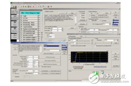
Advanced graphical evaluation and analysis programming tool EasyMoTIon Studio platform to quickly set the motor, drive parameters and programming motion program, TML_LIB function library is a function library of intelligent servo drive to perform motion control applications on PC, in C / C + +, Basic, Delphi, After the LabVIEW development application calls the .DLL file in the library, it can directly communicate with the driver, set parameters, query status, transfer commands, define motion events, and test the status of input and output ports.
Starter Kit for IDM640: Contains the complete components of the drive, including an IDM640 drive, a motor, an I/O board, EasyMoTIon Studio software, and application help and complete documentation. It is the ideal experimental platform for testing your motion control program. Both are included in a ready-to-run, plug-and-play component as described above.
The DC servo motor consists of the following components:
Stator: Magnetic field - permanent magnet
Rotor: armature winding
Reversing: commutator and carbon brush
The DC power supply applied to the Dc Motor, by means of the action of the commutator and the brush, causes the current flowing through the armature coil of the DC motor to be alternating, so that the direction of the electromagnetic torque generated by the armature is constant. Make sure that the DC motor rotates continuously in the determined direction.
5
DC servo advantages:
• Precise speed control
• Torque speed characteristics are very hard
• Simple principle and easy to use
• price advantage
Disadvantages:
• Brush commutation
• Speed ​​limit
• Additional resistance
• Produces wear particles (for clean rooms)
Sex Toy Vibration Motor voltage is lower than 6 v, small size, shaking force is strong, the price is cheap. Concrete can be customized according to the requirements of various parameters of the vibration motor!
Copper
tungsten steel material
plate material
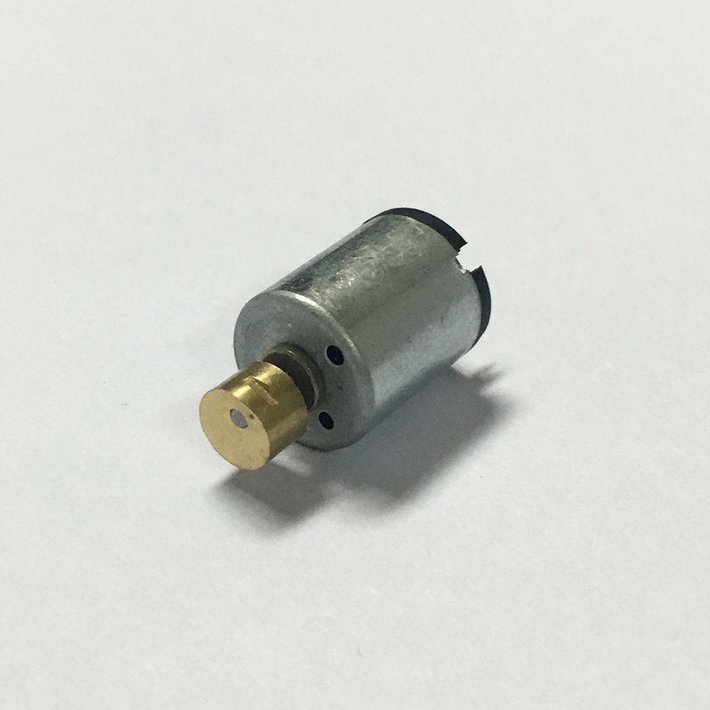
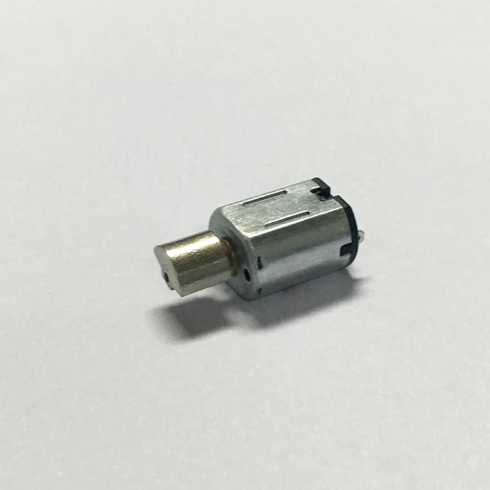
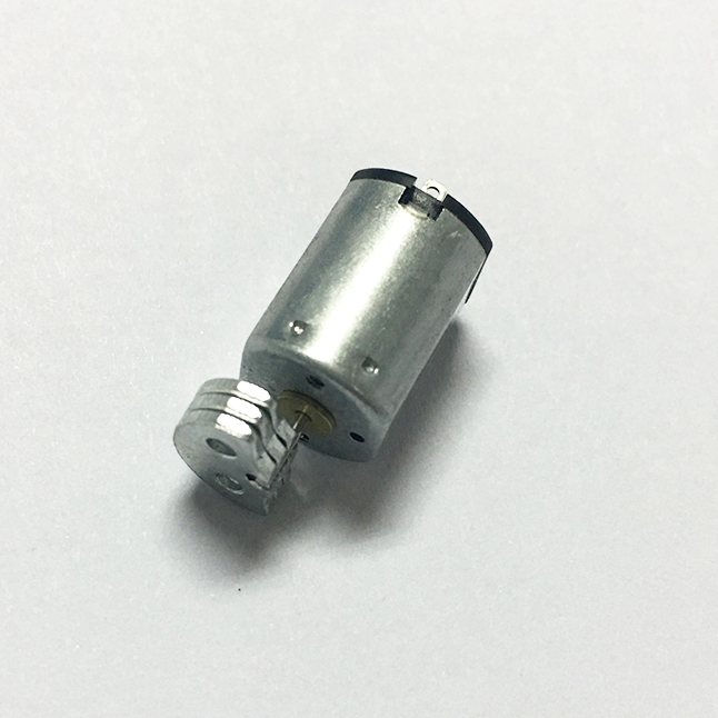
Vibration of the motor head material, copper, tungsten steel material, plate material, place head motor with different material, different vibration strength, the unit price is different
Operating temperature range:
Sex Toy Vibration Motor should be used at a temperature of -10~60℃.
The figures stated in the catalog specifications are based on use at ordinary room temperature catalog specifications re based on use at ordinary room temperature (approximately20~25℃.
If a Micro Vibration Motor For Sex Toy is used outside the prescribed temperature range,the grease on the gearhead area will become unable to function normally and the motor will become unable to start.Depending on the temperature conditions ,it may be possible to deal with them by changing the grease of the motor's parts.Please feel free to consult with us about this.
Storage temperature range:
Sex Toy Vibration Motor should be stored ta a temperature of -15~65℃.
In case of storage outside this range,the grease on the gearhead area will become unable to function normally and the motor will become unable to start.
Service life:
The longevity of Micro Vibration Motor For Sex Toy is greatly affected by the load conditions , the mode of operation,the environment of use ,etc.Therefore,it is necessary to check the conditions under which the product will actually be used .The following conditions will have a negative effect on longevity.Please consult with us should any of them apply.
â—Use with a load that exceeds the rated torque
â—Frequent starting
â—Momentary reversals of turning direction
â—Impact loads
â—Long-term continuous operation
â—Forced turning using the output shaft
â—Use in which the permitted overhang load or the permitted thrust load is exceeded
â—A pulse drive ,e.g.,a short break,counter electromotive force,PWM control
â—Use of a voltage that is nonstandard as regards the rated voltage
â—Use outside the prescribed temperature or relative-humidity range,or in a special environment.
â—Please consult with us about these or any other conditions of use that may apply,so that we can be sure that you select the most appropriate model.
when it come to volume production,we're a major player as well .each month,we rurn out 600000 units,all of which are compliant with the rohs directive.Have any questions or special needed, please contact us, we have the engineer group and best sales department to service to you Looking forward to your inquiry. Welcome to our factory.

Sex Toy Vibration Motor,Micro Vibration Motor For Sex Toy,Dc Sex Toy Vibration Motor,12V Motor For Sex Toy Vibrator
Shenzhen Shunchang Motor Co., LTD. , https://www.scgearmotor.com