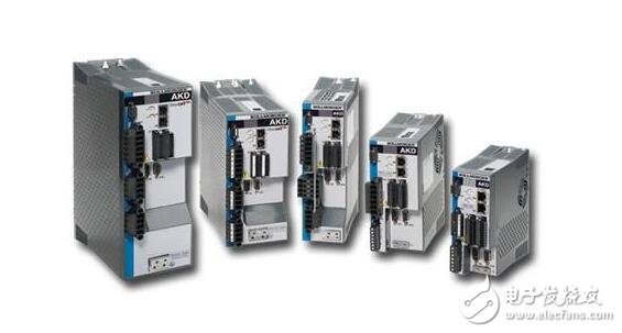
The servo amplifier is a controller used to control the servo motor. Its function is similar to that of the inverter acting on a common AC motor. It is part of the servo system and is mainly used in high-precision positioning systems. Generally, the servo motor is controlled by three modes: position, speed and torque to realize high-precision transmission system positioning. At present, it is a high-end product of transmission technology.
The servo amplifier functions to compare, amplify and calculate the input command signal (voltage) with the system feedback signal (voltage), and then output a control current proportional to the deviation voltage signal to the servo valve torque motor control coil to control the servo valve spool The opening size and the limit protection.
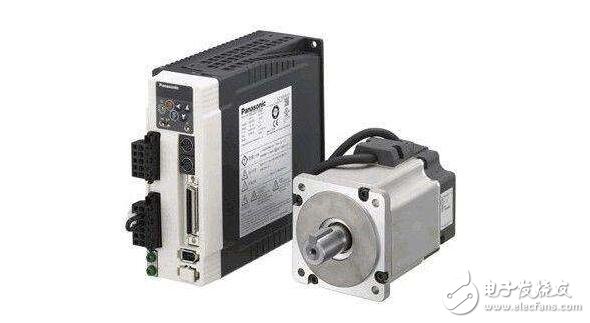
The function of the servo amplifier is to combine and amplify a plurality of input signals and feedback signals, and output corresponding signals according to the polarity of the integrated signal to control the servo motor to rotate forward or reverse. When the input signal and the feedback signal are balanced, the servo motor stops rotating and the output shaft of the actuator is stabilized at a certain position.
The servo amplifier group is composed of a pre-magnetic amplifier, a flip-flop, a thyristor main circuit, and a power supply, and its composition is as shown in the following figure.
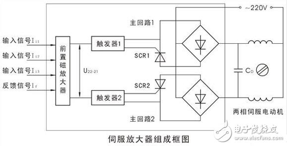
To accommodate the need for complex multi-parameter adjustments, the servo amplifier is configured with three input signal channels and one position feedback signal path. Therefore, it can input three input signals and one position feedback signal at the same time. In a single-parameter simple adjustment system, only one of the input and feedback channels is used.
In the servo amplifier, the pre-amplifier combines the three input signals and one feedback signal into a deviation signal and amplifies it into a voltage signal U22-21 output. The output voltage is simultaneously converted into a trigger pulse by the trigger 1 (or 2) to control the thyristor conduction of the thyristor main circuit 1 (or 2), thereby applying an AC 220V power supply to the two-phase servo motor winding to drive the two-phase servo motor. Turn. When △1》0, U22-21′0, trigger 2 and main circuit 2 work, two-phase servo motor rotates forward; when △1 “0, trigger 1 and main circuit 1 work, two-phase servo motor Inverted; the circuit composition and parameters of the two sets of flip-flops and the two sets of thyristor main loops are identical, so when the input signal is balanced with the position feedback current If, the output of the pre-magnetic amplifier is U22-21≈0, both flip-flops There is no trigger pulse output, the thyristors in the main circuits 1 and 2 are blocked, the power of the two-phase servo motor is turned off, and the motor stops rotating.
It can be seen that the servo amplifier is equivalent to a three-position non-contact relay and has a large power amplification capability.
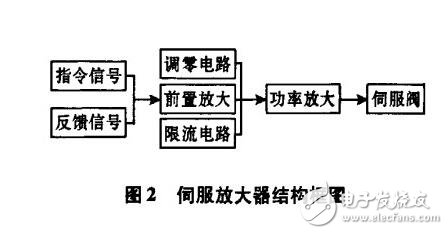
The servo amplifier consists of functional modules such as command and feedback comparison processing, zeroing circuit, current limiting circuit, preamplifier, power amplification, etc. The block diagram of the structure is shown in Figure 2.
The specific circuit schematic of the servo amplifier is shown in Figure 3.
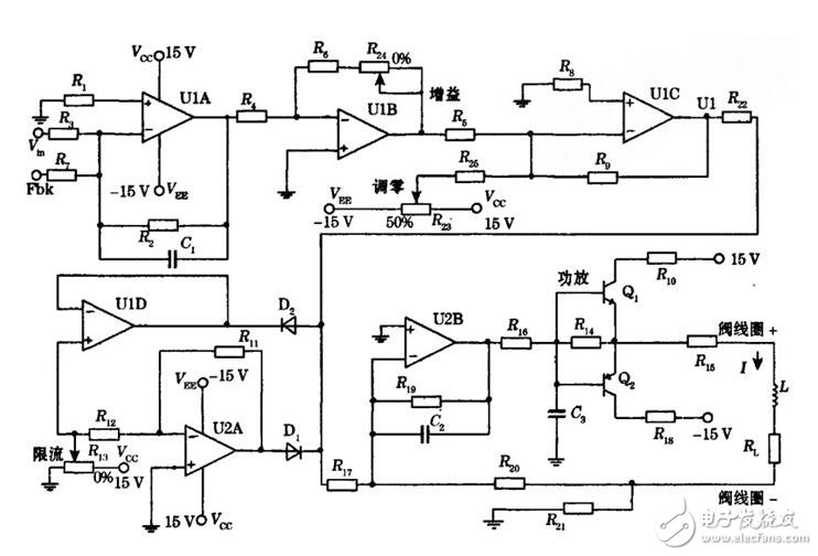
The function of the preamplifier circuit is to compare and amplify the command and feedback input signals. This circuit K. Fbk is the input signal and the feedback signal respectively, and the gain of the circuit is adjusted by the potentiometer j匕 to adapt to the requirements of the power amplifying circuit, so that the circuit voltage is matched before and after. The function of the zeroing circuit is to adjust the circuit reference voltage by superimposing the adjustable voltage on the preamplifier circuit. The servo amplifier system bias is overcome by adjusting the potentiometer such as zero offset compensation.
The function of the current limiting circuit is to limit the maximum current flowing through the coil of the servo valve, avoid overloading the coil, protect the servo valve, and limit the maximum flow of the hydraulic system. The circuit consists of an op amp ulD, U2A, and diode D. , D: and adjustable voltage source, through the potentiometer R. Adjust the amplitude of the input voltage of the power amplifier stage to achieve the purpose of limiting the output current. The function of the power amplifying circuit is to amplify the low power voltage signal into a power signal with a large power to provide sufficient servo valve rated current to drive the load. It also requires good anti-interference ability and static and dynamic performance. The circuit uses the base and emitter stages of the NPN and PNP type transistors to be connected to each other, and the signal is input from the base and the emitter is output. The circuit can be seen as a combination of two emitter outputs, forming a push-pull power amplifier circuit that operates in the positive and negative half cycles of the input signal. In addition, a high-frequency dither signal generated by the 8038 chip can be superimposed on the output current to improve servo valve resolution and prevent spool stuck due to Coulomb friction.
Servo amplifier parameter requirementsAs an electronic device for driving electro-hydraulic servo valves, servo amplifiers have certain requirements:
(1) The input voltage is within ±10 V, which is convenient for the control of computer and programmable controllers;
(2) The output current is ±10±100 n approved to adapt to various types of torque motor servo valves;
(3) The servo amplifier linearity error is less than 3% Fs;
(4) having a feedback access terminal to form a closed loop control system;
(5) In order to adapt to the characteristics of the high frequency response of the servo system, the servo amplifier bandwidth is greater than l 200 Hz;
(6) It has the maximum output current limit and output short-circuit protection function, which can limit the maximum flow of the servo valve and prevent the output line from being short-circuited and cause malfunction.
The servo valve coil is the load of the servo amplifier, which is equivalent to the inductive impedance composed of 0.3 H inductor and 80 Q resistor. In order to make the output control current of the power stage proportional to the input voltage signal, a resistor such as a resistor is used. Connected to the load coil in series, and the voltage on it is fed back to the inverting input of the amplifier through a resistor, such as closed loop control, to precisely adjust the power stage output current. Because the power stage feedback voltage is generated by current, it is called current negative feedback. After the introduction of current negative feedback, the load impedance change does not affect the power stage output current change substantially within the rated load range, and the servo amplifier is equivalent to a constant current source.
According to the principle of the short and virtual break of the op amp, it can be introduced:

Where K is the preamplifier circuit gain.
The servo amplifier output current and input voltage are linear and independent of the load, tending to a constant current source
Solder Wire/bar is an indispensable material for the manufacture of electronic products .Tin wire,TIn bar and tin paste are the most widely used electronic welding materials,the technical level depends on the performance of solder joints and welding process performance.
Product specification: Ñ„12*330mm
295*20*13mm
Product Features:
Smooth surface,neat coiling,beautiful appearance,uniform distribution of additives,good continuity.
Less splash of additives in welding process,good mobility,good wettability,less smoke,less oxide slag,bright welding spots.
Widely used in a variety of wave slidering and manual welding of television,audio capacitors,circuit boadrds and communications equipment.
Including SnCu.SnAg.SnAgCu,SnAgCuSb.SnAgBi series.
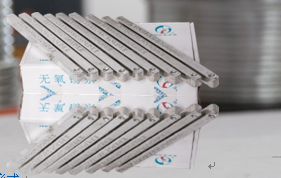

Solder Bar,Solder Wire Bar,Silver Solder Bar,Lead-Free Tin Solder Bar
Shaoxing Tianlong Tin Materials Co.,Ltd. , https://www.tianlongspray.com