What type of microphone is best for a particular application? Should we choose a condenser microphone or a dynamic microphone, is it a omnidirectional or a cardioid pointing microphone, is it a flat frequency response or a specific frequency response? This article will explore the advantages and disadvantages of various types of microphones, and associate these advantages/disadvantages with various types of application scenarios. Understanding these aspects will only help you choose the right microphone.
Ideally, there should be a universal microphone for all applications. But there is actually no such microphone, because each application has different usage requirements. The ideal power amplifier or speaker has a linear transmission characteristic, but the frequency response characteristics of the microphone are usually optimized for certain types of applications.
For example, in order to accurately replicate a tone, a classical music recording engineer needs a microphone with a flat frequency response. However, what a pop music producer might want is a high-frequency partially boosted microphone to get a higher loudness.
For classical music recording engineers, the 41 Hz signal is music; for voice broadcast engineers, the sound in this band is noise. Therefore, microphones for classical music recording have good low-frequency response characteristics, while microphones for speech signal pickup use a roll-off design at low frequencies.
Closer to this, singers on the stage usually like to use a microphone that can raise the low frequency (near talk effect) to make the sound sound warmer and more powerful. A microphone with the same characteristics is used in the studio without equalization, which makes the sound of the instrument sound turbid.
In addition, there are many different types of microphone pointing characteristics designed according to different application requirements. Omni-directional microphone – picks up sound in all directions and is suitable for picking up the reverb sound of the concert hall. Compared to omnidirectional microphones, the single-pointing microphone picks up less reverberation and sound leakage, and is suitable for occasions where external noise affects the quality of sound pickup, such as live recording.
These design changes have made the design and use of the microphone layout very interesting.
Every microphone needs to have the characteristics
What we have just talked about is the need for microphones with different frequency response characteristics and pointing characteristics. However, all microphones need to have the following commonalities:
Low noise floor with high dynamics (can withstand high sound pressure without distortion)
Better mechanical noise with low RF interference capability (friction during hand)
Lower wind noise and pop noise (explosive breathing)
Minimize off-axis acoustic staining (consistent frequency response characteristics in both axial and off-axis directions)
High sensitivity
These characteristics are necessary for obtaining a clear sound: no noise, no distortion, and no sounding in the off-axis direction. Some other feature requirements, such as:
Small size (sometimes)
Strong directivity (sometimes)
Rugged and low cost
Unfortunately, it is impossible for us to concentrate all of the above requirements in one microphone because of the conflict between these feature requirements. For example, if a larger grid cover is used to eliminate pop noise, the overall size of the microphone will become too large; if the headroom is added by adding a built-in attenuation circuit, the signal-to-noise ratio will be reduced.
In general, every design decision is made for compromise. An increase in the characteristics of one aspect means that the characteristics of the other aspect are limited.
The purpose of this paper is to describe these design tradeoffs so that microphone users can better understand which features are more important in a given usage scenario. By understanding the design trade-offs, we can choose the right microphone more wisely.
A compromise in microphone design
Microphone type overview
First, let's take a look at how different types of microphones convert sound into electrical signals. Microphones used in professional fields can be divided into two types according to their working principle: moving coils or condenser microphones. In a moving coil microphone, an electric signal is generated by cutting a magnetic line of force through a movable conductor. The dynamic microphone is divided into two types: a dynamic coil microphone and a belt microphone.
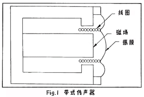
A moving coil microphone (commonly referred to as a moving coil microphone) is shown in Fig. 1. A coil connected to the diaphragm is suspended within the magnetic field. When the sound waves vibrate the diaphragm, the coil also vibrates within the magnetic field to produce an electrical signal that is similar to the input sound wave.
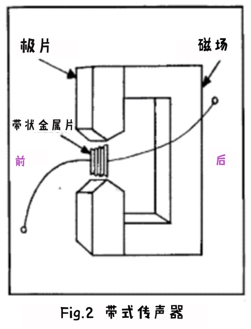
The belt microphone is shown in Fig. 2, a very thin metal foil or strip of metal is suspended in the magnetic field. The sound waves cause the metal piece suspended in the magnetic field to vibrate and thereby generate an electrical signal.
The condenser microphone is shown in Fig. 3. A conductive diaphragm and a metal plate (back electrode) are connected to the two poles of the capacitor. When the sound wave vibrates the diaphragm, the volume between the diaphragm and the metal backplate is changed. This change changes the capacitance and thus the electrical signal similar to the input acoustic wave.
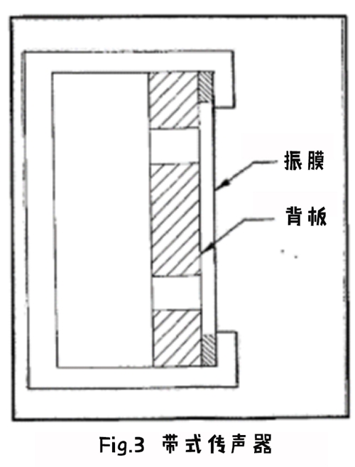
The diaphragm and metal back plate can be powered by external devices or by an insulator embedded in the diaphragm or metal back.
How to choose between capacitors, belts and moving coil microphones
The differences in physical structure make these three types of microphones have different performance characteristics.
When you have the following usage requirements, the better choice is the condenser microphone:
Excellent transient response (for example, for sound instruments such as percussion instruments, cymbals, acoustic instruments, and large ensembles)
High sensitivity (for long-distance pickup of sound sources with low original volume)
Wide operating frequency band and smooth frequency response curve (suitable for most studios that require faithful reproduction of the natural sound quality of the sound source)
Smaller volume (collar microphone or interface microphone)
When you have the following usage requirements, the better choice is the dynamic microphone:
Slower transient response (attenuation of excessive detail, such as close-up pickup of woodwind or brass)
Lower price (usually, the price of a moving microphone is lower than that of a condenser microphone)
Rugged and durable to withstand high sound pressure (for example, for electric guitar speakers or drum kits)
Low noise floor is less affected by temperature and humidity, higher reliability (no power required)
When you have the following usage requirements, the better choice is the belt microphone:
Warm, smooth sound (for example, when listening to brass instruments at close range, the sound can be made less "sharp")
It should be noted that the performance attributes of the different types of microphones described above are general trends. For example, some dynamic microphones also have smooth frequency response characteristics or high sensitivity characteristics, and some condenser microphones have better dynamic margin and are durable. The microphone selection described above is based on the commonality of each type of microphone.
Frequency response characteristics of different types of transducers
In the chart below, the leftmost column shows the diaphragm velocity (solid line) corresponding to the frequency of the four transducers or the diaphragm displacement (dashed line) corresponding to the frequency.
The middle column shows the relationship between the pressure gradient (the difference in acoustic pressure at the front and rear ends of the diaphragm) and the vibration of the diaphragm. For omnidirectional microphones, the rear end of the diaphragm is a sealed outer casing, so the relationship between differential pressure and frequency is constant. For a single-point or two-point (pressure step) microphone, the back end of the diaphragm is affected by the sound wave, and there is a time difference between the sound wave reaching the front end of the diaphragm, so the pressure difference increases as the frequency increases.
The column on the right shows the result of the addition of the diaphragm velocity and pressure gradient (dynamic microphone) or the result of adding the diaphragm displacement to the pressure gradient (capacitor microphone). The result after the addition is the amplitude/frequency response characteristic of the microphone.
Figure A shows the omnidirectional moving coil (omnidirectional moving coil) transducer. This type of transducer is damped to the intermediate frequency resonance, so the relationship between diaphragm speed and frequency variation remains relatively constant. The output voltage is proportional to the diaphragm speed. The pressure step and the frequency change at both ends of the diaphragm are also in a constant state because the rear end of the diaphragm is located in the sealed space. Therefore, this type of microphone maintains a flat response characteristic over most of the audio signal frequency range.

Figure A
Figure B shows the omnidirectional capacitive transducer. This type of transducer is damped to the resonance of the high frequency portion. The rate of the diaphragm is increased by 6 dB per octave, so the relationship between the amplitude of the diaphragm displacement and the change in frequency remains constant. The output voltage is proportional to the amplitude of the diaphragm displacement. The relationship between the pressure step and the frequency change remains constant, thus maintaining a flat frequency response characteristic over most of the audio signal frequency range.

Figure B
Figure C shows a single-pointed moving coil transducer. This type of transducer is damped to low frequency resonances, and its diaphragm rate maintains a 6 dB drop in octave over most of the frequency range. The output voltage is proportional to the diaphragm speed. However, since the pressure step is increased by 6 dB per octave in the mid-high frequency band, flat frequency response characteristics are maintained over most of the audio signal frequency range.

Figure C
Figure D shows a single pointing capacitor transducer. This type of transducer is damped to the intermediate frequency resonance. The relationship between the diaphragm rate and the frequency change remains constant, and the diaphragm displacement maintains a 6 dB drop in octave over most of the frequency range. The output voltage is proportional to the diaphragm displacement. However, since the pressure step maintains a 6 dB increase per octave over most of the frequency range, flat frequency response characteristics are still obtained.

Figure D
Advantages and disadvantages of various microphones
Let's examine the performance of the microphone in several ways, and look at the different types and disadvantages of different types of microphones in each of the tested aspects.
Transient Response – Due to the small diaphragm quality and high damping of the condenser microphones, they respond faster to moving coils than transient microphones (transient). When using a high-performance condenser microphone, we can hear the “click†sound when tapping the cymbal or the plucking sound when playing the guitar chord. Capacitive microphones provide clear, detailed sound, making them ideal for use in cymbals, snares, acoustic instruments, and vocal recordings.
In general, the transient response of a moving coil microphone is weaker than that of a condenser microphone. Therefore, dynamic microphones can be used in applications where it is necessary to "soften" the sounds that are too rich in detail.
Frequency Response – Capacitive microphones typically provide a smoother frequency response due to the relatively simple design of the transducer structure. Similarly, due to the relatively simple structure, the band-free microphone's peak-free frequency response makes it widely acclaimed. In addition, the metal foil diaphragm of the belt microphone is designed to be corrugated to reduce the chance of breakage.
In contrast, in addition to some very good dynamic microphones, the frequency response characteristics of dynamic microphones are generally not as flat as condenser microphones or ribbon microphones. The transducer structure of the moving microphone includes a coil that can be disengaged from the diaphragm piston mechanism, or a coil that can move back and forth. This structural characteristic makes the frequency response characteristic of the moving coil microphone have a peak limit. In addition, since the coil acoustically divides the diaphragm mechanism into two acoustic cavities, it resonates with the magnetic gap inertia and causes an abnormal frequency response. The diaphragms of condenser microphones and ribbon microphones are also separable, but generally have a lower impact on the frequency response.
Due to the small diaphragm quality, condenser microphones typically provide better high frequency response than belt or moving coil microphones. Although the diaphragm quality of the belt microphone is small, the acoustic phase interference between the front end and the rear end of the diaphragm causes an offset in the high frequency region. This is because the wavelength of the high-frequency part is very short, and the signals on both sides of the belt diaphragm may have opposite polarities, thus causing acoustic cancellation. Due to structural design, this problem does not occur in capacitors or moving coil microphones. The high frequency energy behind the diaphragm is either attenuated by the microphone housing (omnidirectional microphone) or eliminated by the acoustic phase shifting network (single pointing microphone).
The high frequency response of the dynamic microphone can be extended by a Helmholz resonator placed in front of the diaphragm. The Helmholz resonator is a small-sized air chamber with one or more acoustic wave inlets. The resonance generated in the high-frequency part can improve the high-frequency response of the moving coil microphone. However, this design still has some limitations, and attenuation and a higher degree of phase shift occur in the frequency band above the resonance point of the resonator. Helmholz resonators are also often used in condenser microphone designs, but in general the required high frequency energy boost is less than that of moving coil microphones.
Sensitivity – In general, condenser microphones have the highest sensitivity, followed by moving coil microphones, while belt microphones have the lowest sensitivity. The following are typical open circuit sensitivity parameters for these three types of microphones:
Capacitor microphone: -65 dBV (5.6 mV/Pa)
Dynamic microphone: -75 dBV (1.8 mV/Pa)
Belt microphone: -80 dBV (1 mV/Pa)
The reason that the sensitivity of the condenser microphone is higher than that of the dynamic microphone is that the transducer of the condenser microphone is more efficient in design, and the corresponding preamplifier is built in to enable higher gain.
The output voltage of the condenser microphone can be calculated by the following formula:

among them:
V = voltage across the capacitor â–³V = voltage variable or output signal voltage
C = capacitance between the diaphragm and the back electrode in Farad ΔC = the capacitance change due to diaphragm movement reduces or increases the capacitance distance
The higher the voltage, the higher the sensitivity. However, an excessively high voltage causes the diaphragm to be adsorbed on the back electrode due to electrostatic repulsion, which hinders the vibration of the diaphragm.
The greater the change in capacitance, the greater the voltage change (that is, the greater the output signal voltage). The larger the area of ​​the diaphragm or the smaller the distance between the diaphragm and the back electrode, the greater the change in capacitance. Unfortunately, large-diameter diaphragms are susceptible to acoustic staining in the off-axis direction due to diffraction and other factors; reducing the distance between the diaphragm and the back electrode is very difficult and expensive, requiring careful avoidance during assembly. The dust particles enter the cavity between the diaphragm and the back electrode. Therefore, microphone manufacturers must find an appropriate compromise solution.
In order to obtain sufficient sensitivity, dynamic microphones also need to find a solution from this design. The output voltage formula of the moving microphone is as follows:

among them:
e = output voltage (induced electromotive force)
B = flux density in Tesla
l = conductor length in meters
v = speed of movement in meters per second
The higher the magnetic flux density, the higher the number of turns of the coil and the higher the output voltage. However, an oversized magnet may acoustically affect the frequency response characteristics and also increase the size and weight of the microphone. Similarly, too many turns of the coil will increase the quality of the moving coil mechanism, resulting in degradation of the microphone response to high frequencies. If a higher magnetic flux density is obtained by reducing the magnetic gap, it is difficult to ensure that the coil does not rub against the magnetic pole. It is worth mentioning that new magnet materials such as samarium-cobalt magnets can produce higher magnetic flux densities in smaller volumes.
The reason that the sensitivity of the belt microphone is lower than that of the dynamic microphone is that the belt microphone has only one low-impedance conductor (band metal foil) to generate an electrical signal, and a large-sized magnet and a booster are required to increase the output voltage. In addition, the strip-shaped metal foil is driven by the differential pressure (pressure step) on both sides of the diaphragm, which is even smaller than the single-point design of the moving-coil microphone for the bidirectional ribbon microphone design.
Dimensions – Capacitor microphones can be much smaller than dynamic microphones. Dynamic microphones require a certain volume of magnets and voice coils to provide sufficient output voltage, but even condenser microphones with a diaphragm area of ​​less than 1 cm2 provide sufficient output voltage.
Maximum Sound Pressure Level – A well-designed moving coil microphone can withstand very large sound pressures without excessive distortion at the output. Even a very high sound pressure will only cause a slight vibration of the diaphragm. However, the electrical components used in the condenser microphone are susceptible to overload due to electrical signals generated by the transducer. If an attenuator is inserted between the transducer and the electrical component to avoid overload (for example, to increase the maximum sound pressure level), the signal-to-noise ratio will decrease accordingly. If the dynamic headroom of the microphone electrical components is maximized, it usually costs the more current and the higher noise floor. The transducer manufacturer must consider all of these influencing factors and determine the appropriate design for the application.
Noise floor – Since there are no components that require external power supply, the noise floor of the dynamic microphone is very low compared to condenser microphones. The open circuit noise voltage generated by the moving microphone can be calculated by the following formula:

among them:
E = noise signal voltage in volts
k = Boltzmann constant (1.38 x 10⁻²³ J/K)
R = internal resistance of the microphone in ohms
T = temperature in Kelvin ΔF = frequency bandwidth in Hertz
The higher the microphone output impedance (measured at a particular frequency, measured at the microphone connection terminal), the greater its noise floor. The noise floor can be calculated by the following equation:
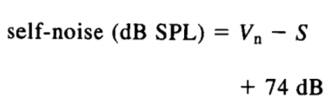
among them:
Vn = noise signal voltage in dBV
S = microphone sensitivity in dBV/μbar
For example, if a microphone with a noise signal voltage of -133 dBV and a sensitivity of -75 dBV/μbar has a noise floor of 16 dB SPL. This value is calculated based on the unweighted measurement results. If the A-weighting parameter is required, it needs to be measured by a weighted network that simulates the human ear frequency response curve (rolling down at frequencies below 1 kHz). The value calculated from the A-weighted measurement result is relatively closer to the human ear.
A condenser microphone with a very low noise floor is 14 dBA. A condenser microphone is generally considered to be excellent if it has a noise floor of less than 20 dBA; if it is below 30 dBA, it is generally considered to be a good performance condenser microphone.
Power System Requirements – Capacitor microphones require an external power supply system to operate, such as a battery or an external phantom power system. The phantom power is 12 – 48 V DC transmitted through pin 2 and pin 3 of the microphone connector. The microphone uses the same two wires to receive phantom power and send audio signals. Many consoles support phantom power to the microphone through their signal input connectors. Users only need to connect the microphone to the mixer's input port to obtain phantom power.
In contrast, dynamic microphones do not require any power supply system to operate, so reliability is higher.
Balanced and durable – A well-designed dynamic microphone is generally very durable and can perform well under certain conditions of harsh use. Some modern condenser microphones also have the same durability, although their complex electrical components may look fragile. On the contrary, the belt diaphragm is very fragile, and strong wind or bad habits may cause the diaphragm to deform.
High temperatures and high humidity can cause electret damage, but they have little effect on moving coil transducers. Excessive humidity can cause the narrow space between the diaphragm of the condenser microphone and the back electrode to be filled with moisture, which can cause the transducer to fail. For a moving coil transducer, the gap between the coil and the magnet is large, so the influence is less in a high humidity environment.
Pointing feature
Different types of pointing characteristics (pointing picking patterns) also have their own advantages and disadvantages. Before going any further, let's review the common microphone pointing characteristics.
Pointing to feature overview
The omnidirectional microphone has the same sensitivity for sounds coming from all directions; the single-pointed microphone is only sensitive to sounds coming from one direction (the sound coming from the front of the microphone and the sound coming from the side or the rear) The sensitivity is low; the bi-directional microphone is the most sensitive to the sound coming from both directions – front and rear, but attenuates the sound from the side. Figure 4 shows the different types of microphone pointing characteristics.
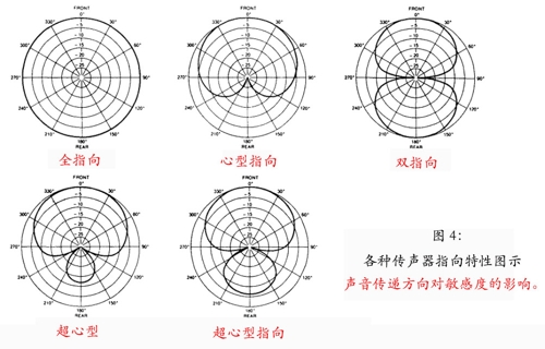
Figure 4
A single directionalizer can be subdivided into three subtypes: heart, supercardi, and mixed heartpoint. The cardioid-pointing microphone is more sensitive to sound in the wider front range, with a sensitivity attenuation of 6 dB on the side and a sensitivity attenuation of 15 – 25 dB on the rear. The supercardioid pointing microphone attenuates lateral sound waves by 8.7 dB and two zero pick-up areas in the 125-degree axial region. The hybrid cardioid pointing microphone attenuates the lateral sound waves by 12 dB and two zero pick-up areas in the axial 110 degree region.
Because they isolate sound waves from the rear and side, single-point and dual-point microphones help the user remove unwanted sounds such as room reflections, feedback or sound leaks (from other instruments located in the off-axis area of ​​the microphone). These microphones maintain good acoustic isolation or separation between the sound tracks.
After the slotted tube (wave interference tube) is attached to the front end of the acoustic cavity of the hybrid cardioid microphone, it becomes a super-directional microphone, such as a gun microphone or a linear pointing microphone. These microphones are commonly used for long-distance pickup of speech signals during film production, television production, and news interviews.
Near-talk effect
When the distance from the sound source is very close, most single-pointing and bidirectional microphones will have a low-frequency partial boost. The most common is that when the singer sings at a distance close to the microphone, the sound becomes more generous. This phenomenon in which the low frequency portion is improved due to the proximity of the sound source is called a near-talk effect. This phenomenon usually occurs on a single-point microphone of the single-D type. The diaphragm of this type of microphone has a fixed distance from the front and rear sonic inlets.
The near-talk effect can make the drum sound warmer and fuller. However, in most recording applications, the near-talk effect can cause the sound or vocals of the instrument to be too turbid and unnatural. In order to reduce the impact of the near-talk effect, some specially designed Multiple-D type microphones have begun to appear; other types of microphones use the built-in low-frequency roll-off switch to gain compensation for low-frequency boosting. Of course, the user can also use the equalizer on the mixer to attenuate too much low-frequency energy, and also attenuate the low-frequency energy in the sound leakage picked up by the microphone.
Choose the microphone that points to the most appropriate feature
Some of the features of omnidirectional microphones make them ideal for use in certain features. In the following applications, using a omnidirectional microphone is a good choice:
The omnidirectional pickup picks up the reverberation sound of the room, hoping to reduce the low-frequency response (capacitor microphone) that pop sound (explosive breathing sound) has less influence on sound pickup.
Relatively low cost
In the following applications, using a single pointing microphone is a good choice:
Selective sound pickup to avoid the effects of room reverberation, background noise, and acoustic leakage. The near-talk effect helps the sound quality when used with a sound reinforcement system to obtain better pre-feedback gain-synchronized stereo pickup.
In the following applications, the use of a cardioid pointing microphone is a good choice:
Pick up the sound source in a wide area in front of the microphone to maximize the isolation of sound from behind the microphone
In the following applications, the use of a supercardioid pointing microphone is a good choice:
ï‚ Need to maximize the difference in sound pickup between the first half and the second half, seeking an appropriate balance between isolating the sound from the rear (from the ground return speaker) and the random burst of sound (from the main PA system speaker)
In the following applications, a hybrid heart-shaped pointing microphone is a good choice:
It is desirable to achieve lateral isolation with a single pointing microphone to maximize room isolation, sound leakage, feedback, and background noise. Hybrid cardioid microphones have the best random energy efficiency (optimal isolation for random bursts of sound).
In the following applications, using a two-directional microphone is a good choice:
It is necessary to simultaneously pick up the sound signals in front of and behind the microphone, and also to isolate the lateral sounds (for example, face-to-face interviews)
Blooming stereo scanning method for lateral sound when picking up the symphony orchestra sound signal in an axially downward tilting and hoisting manner
In the following applications, the use of gun microphones is a better choice:
Pick up the sound signals you need from a distance. Long-distance pickup in movies, TV and news production. Maximize isolation of background noise and room reflections.
It should be noted that both the capacitor and the moving coil microphone can be designed to have any directional characteristics (except for the bidirectional moving coil design). The belt microphone is either a two-point design or a hybrid cardioid pointing design. Figure 5 is a table of microphone classifications based on transducer type and directional characteristics.

How the directional characteristics are formed
Different types of vents, air tubes, and damping materials are placed behind the microphone diaphragm, which allows the microphone to respond to sounds from different directions.
The omnidirectional microphone (capacitor or moving coil) is designed to be open only at the front end of the diaphragm, so the diaphragm responds only to pressure from the outside. The acoustic wave pressures reaching the front end of the diaphragm from all directions are equal, so the output voltage of the microphone is the same for the sound signal reaching the front end of the diaphragm from any angle, that is, the microphone is correct for the sound from all directions. Have the same response characteristics. However, in the high frequency portion, the directional characteristic of the omnidirectional microphone becomes double pointing, since the microphone itself is an obstacle to the high frequency portion of the sound wave.
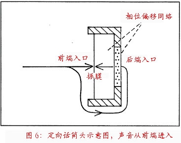
In contrast, single-point microphones (capacitors or moving coils) have an open design on both sides of the diaphragm. The diaphragm is driven by the pressure difference between its front and back sides. There is an acoustic phase shift network (RC or RLC low pass filter) at the rear entrance of the diaphragm. This filter produces a constant delay below its corner frequency. This constant delay is what causes the microphone to produce a single directional characteristic: the sound wave not only squeezes the diaphragm from the front end, but also squeezes the diaphragm from the rear entrance, the time difference between the sound wave reaching the front end and the back end and the phase at the rear end entrance. The offset network produces a phase offset. Therefore, the diaphragm is simultaneously subjected to sound waves reaching the front end and phase-shifted rear end sound waves (Fig. 6). The diaphragm is driven to vibrate due to the instantaneous pressure difference generated by the phase shift on both sides of the diaphragm.
The sound waves coming from the rear reach the diaphragm position of the microphone through two paths: 1) bypassing the microphone cavity and reaching the front end of the diaphragm, 2) passing through the rear entrance and phase offset network. The acoustic signal is added to the internal delay generated by the external delay and phase offset network generated by the acoustic radiation that needs to bypass the microphone cavity (Figure 7).
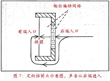
In the cardioid-pointing microphone design, the internal delay is set equal to the external delay, so the sound waves reach the front and back of the diaphragm at the same time. Since the sound waves transmitted from the front and the sound waves transmitted from the rear are opposite in polarity, a canceling phenomenon occurs, so that the sound waves transmitted from the rear do not generate or generate a very small output voltage. This is the principle that the heart type points to the microphone to isolate the rear sound signal.
The phase offset network only works for bands below the mid-high frequency. For sound signals above the mid-to-high frequency range, the microphone cavity itself is a physical obstacle that isolates high-frequency signals from the rear.
Other types of directional characteristics can be formed by scaling the external delay and internal delay (by adjusting the spatial size of the acoustic inlet and acoustic optimization). Each directional characteristic has a specific angle at which the two delays are equal (which produces an offset). The best offset angle for the bidirectional microphone is on the side (90o off axis), the best offset angle for the cardioid pointing microphone is at the back end (180o), and the best offset angle for the mixed cardioid pointing microphone is 110o.
In general, the directional characteristics of a microphone can be calculated by the following equation:
among them:
r = output amplitude at angle φ (r=1 when angle is 0o)
A/B = ratio of internal delay to external delay, A+B=1
φ = angle at which the sound wave is transmitted, 0o is the sound wave is transmitted from the axial direction of the microphone (directly in front of the microphone)
The following results can be obtained by the above equation:
Omnidirectional microphone: r = 1
Heart-shaped pointing microphone: 0.5 + 0.5 cosφ
Supercardioid pointing microphone: 0.366 + 0.634 cosφ
Mixed heart-shaped pointing microphone: 0.25 + 0.75 cosφ
Double pointing microphone: cosφ
It should be noted that for a bidirectional microphone A = 0, because this type of microphone has no phase offset network; for omnidirectional microphones B = 0, because the back end of this type of microphone diaphragm is in the seal Cabin. For cardioid-pointing microphones, A/B = 1.
The advantages of omnidirectional microphones
The omnidirectional microphone has several advantages that make it a good first choice for regular applications. Due to its simple structure (no back-end entry or phase-shifting network), omnidirectional microphones are typically less expensive than directional microphones and provide a smoother frequency response curve. In addition, omnidirectional microphones are 15 to 20 dB less sensitive to mechanical noise and pop noise than single directional microphones. The reason is that the omnidirectional dynamic microphone has a resonant frequency of approximately 500 – 1000 Hz, and a large damping attenuation treatment is targeted. The resonant frequency of a single pointing microphone is about 150 Hz, and the damping attenuation processing is small, so low frequency mechanical shock is more likely to cause diaphragm vibration.
For omnidirectional condenser microphones of any size, the stiffness of the diaphragm mechanism is controlled below the resonant frequency (typically 8 – 10 kHz). The rate of the diaphragm maintains a 6 dB improvement per octave before reaching the resonant frequency (Figure 8). Since the diaphragm displacement produces the layer velocity, the diaphragm displacement amplitude is constant with the frequency change when it is lower than the resonance frequency. The output voltage is proportional to the diaphragm displacement, so the output voltage is also kept constant with the frequency change below the resonance frequency.
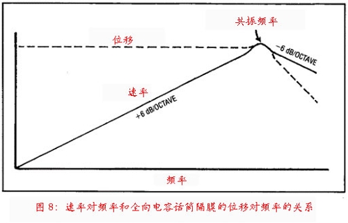
In other words, the omnidirectional condenser microphone can provide a smooth frequency response curve in the frequency band below the resonance frequency (except for the intentional roll-off processing of the low frequency). This feature is common to all sizes of microphones (although the smaller size for the speakers means that the low frequency response is limited, even miniature omnidirectional microphones provide smoothness in frequencies as low as about 20 Hz. Frequency response curve).
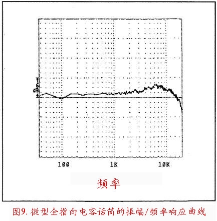
Figure 9 shows the amplitude/frequency response curve of a miniature omnidirectional condenser microphone.
In contrast, microphones with a directional design typically have a tendency to roll off in the low frequency portion, especially when the source is only a few feet away. This is because the microphone diaphragm with the directional design is driven by the differential pressure between the front end and the rear end of the diaphragm. For the low frequency part of the sound wave, the pressure formed at the front end and the rear end of the diaphragm is in phase. Since the instantaneous pressure acting on both sides of the diaphragm is almost equal, the vibration amplitude of the diaphragm is very small, which means that the output voltage is very low.
In addition, the omnidirectional microphone has a lower degree of acoustic staining in the off-axis area relative to a single pointing microphone. The omnidirectional microphone exhibits acoustic staining in the off-axis direction as a roll-off in the high frequency portion. The larger the diaphragm size, the larger the high-frequency energy roll-off. In addition to the high-frequency roll-off feature, the acoustic staining of the off-axis area of ​​a single-pointed microphone also causes peaks and troughs throughout the frequency response range. This is caused by the phase relationship between the sound waves reaching the front end and the rear end of the diaphragm being inconsistent with the frequency variation.
Diaphragm size
In some applications, large diaphragms (diaphragm diameters over 1 cm) have more advantages than small diaphragms, and vice versa.
Choose the right diaphragm size
Among the following applications, choosing a large diaphragm microphone is a good choice:
I hope that a directional design microphone can provide an extended low frequency response (usually)
ï‚ Reduce sensitivity to wind noise and pop noise, obtain higher sensitivity, obtain lower noise floor, and obtain higher signal-to-noise ratio
The latter three characteristics are interrelated: the larger the diaphragm size, the more the transducer can provide an audio signal that is higher than the noise floor energy produced by the electrical components of the microphone itself.
In the following applications, choosing a small diaphragm microphone (micro microphone) is a good choice:
I don't want the microphone to affect the visual effect (fixed on the newscaster or the instrument with a clip)
进行 steadily pick up the continuously moving sound source (fixed to the newscaster or instrument with a clip)
ï‚ Minimize the effect of off-axis acoustic staining on sound quality (pick up a wide-angle source, such as a large choir or a cymbal in a drum kit)
ï‚ åœ¨å¯¹å£°æºé‡‡ç”¨ç•Œé¢æ‹¾å–æ–¹å¼æ—¶ï¼Œå¸Œæœ›èŽ·å¾—扩展的高频å“åº”ï‚ åœ¨å¯¹å£°æºé‡‡ç”¨ç•Œé¢æ‹¾å–æ–¹å¼æ—¶ï¼Œå¸Œæœ›åœ¨æ•´ä¸ªé¢‘率范围内获得一致的指å‘特性
å¾®åž‹ä¼ å£°å™¨çš„ä¼˜åŠ¿
对于尺寸较大的åŒç±»ä¼ 声器æ¥è¯´ï¼Œå°åž‹å…¨æŒ‡å‘ä¼ å£°å™¨çš„ç¦»è½´å£°æŸ“è‰²ç¨‹åº¦è¾ƒä½Žï¼ˆé«˜é¢‘æ»šé™ï¼‰ã€‚åŽŸå› åœ¨äºŽï¼šç”±äºŽè¡å°„çš„åŽŸå› ï¼Œè½´å‘上的高频能é‡å‡ºçŽ°æå‡ï¼Œè€Œåœ¨ç¦»è½´åŒºåŸŸåˆ™ä¸ä¼šå‡ºçŽ°æå‡ã€‚
当振膜直径ç‰äºŽ1个波长时,相对应的频率能é‡æå‡æœ€å¤§ã€‚对于å°æŒ¯è†œä¼ 声器æ¥è¯´ï¼Œæœ€å¤§èƒ½é‡æå‡çŽ°è±¡å‘生在å¯é—»é¢‘æ®µä¹‹ä¸Šï¼›å¤§æŒ¯è†œä¼ å£°å™¨çš„é«˜é¢‘èƒ½é‡æœ€å¤§æå‡çŽ°è±¡é€šå¸¸å‘生在11 – 18 kHzï¼Œå› æ¤å¯¹äºŽå¤§æŒ¯è†œä¼ 声器æ¥è¯´ï¼Œè½´å‘和离轴区域的高频å“应å˜åŒ–更容易被察觉。æ¤å¤–,å°æŒ¯è†œä¼ 声器在离轴区域的相ä½å·®å°äºŽå¤§æŒ¯è†œä¼ å£°å™¨ï¼Œå› æ¤åœ¨å…¶ç¦»è½´åŒºåŸŸçš„高频部分产生的抵消更少。简å•çš„说,æ¢èƒ½å™¨å°ºå¯¸è¶Šå°ï¼Œç¦»è½´åŒºåŸŸçš„高频滚é™å¹…度越å°ã€‚
å°åž‹æŒ‡å‘æ€§ä¼ å£°å™¨åœ¨ç¦»è½´åŒºåŸŸçš„å£°æŸ“è‰²ç¨‹åº¦ä½ŽäºŽå¤§å°ºå¯¸æŒ‡å‘æ€§ä¼ å£°å™¨ã€‚åŽŸå› æ˜¯ï¼šå¤§å°ºå¯¸ä¼ å£°å™¨çš„æŒ‡å‘特性在低频部分是通过相ä½å移网络实现的,在高频部分则通过è¡å°„实现;而å°å°ºå¯¸ä¼ 声器的指å‘特性å³ä¾¿æ˜¯åœ¨éžå¸¸é«˜çš„频段也是通过相ä½å移网络实现的。
由于使相ä½å移网络产生的相ä½å·®ä¸Žé€šè¿‡è¡å°„产生的相ä½å·®ç›¸ç‰éžå¸¸å›°éš¾ï¼Œå› æ¤å¤§å°ºå¯¸ä¼ 声器的指å‘特性会éšç€é¢‘率的å˜åŒ–而å‘生å˜åŒ–。对于å°å°ºå¯¸ä¼ 声器æ¥è¯´ï¼ŒæŒ‡å‘特性在大部分å¯é—»é¢‘段内都å¯ä»¥é€šè¿‡ç›¸ä½åç§»ç½‘ç»œè¿›è¡ŒæŽ§åˆ¶ï¼Œå› æ¤å…¶æŒ‡å‘特性与频率之间的关系能够ä¿æŒç›¸å¯¹æ’定。由æ¤äº§ç”Ÿçš„结果就是,å°å°ºå¯¸ä¼ å£°å™¨åœ¨ç¦»è½´åŒºåŸŸçš„å£°æŸ“è‰²ç¨‹åº¦ä½ŽäºŽå¤§å°ºå¯¸ä¼ å£°å™¨ã€‚
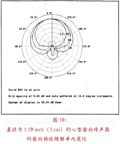
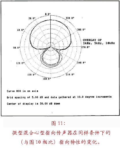
图10显示了一支振膜直径为1.19-inch(3 cm)的心型指å‘ä¼ å£°å™¨çš„æŒ‡å‘特性éšé¢‘率å˜åŒ–而å‘生å˜åŒ–的情形。图11显示了一个微型混åˆå¿ƒåž‹æŒ‡å‘ä¼ å£°å™¨åœ¨åŒæ ·æ¡ä»¶ä¸‹çš„指å‘特性å˜åŒ–情况。从图ä¸æˆ‘们å¯ä»¥æ¸…楚地看到,尺寸较å°çš„ä¼ å£°å™¨çš„æŒ‡å‘特性在频率å˜åŒ–æ—¶ä¿æŒäº†è¾ƒé«˜çš„一致性,尤其是在å‰åŠåŒºã€‚
在被安装在一个åå°„é¢ä½œä¸ºç•Œé¢ä¼ 声器使用时,å°å°ºå¯¸ä¼ 声器能够æä¾›æ¯”å¤§å°ºå¯¸ä¼ å£°å™¨æ›´å¹³æ»‘çš„é«˜é¢‘å“应特性。原ç†å¦‚下:在一些界é¢ä¼ 声器的结构当ä¸ï¼Œä¼ 声器的æ¢èƒ½å™¨çš„轴线与边界平é¢å¹³è¡Œï¼ŒæŒ¯è†œçš„ä¸è½´ç•¥é«˜äºŽè¾¹ç•Œå¹³é¢ã€‚å› æ¤ï¼Œç•Œé¢å射声到达振膜的时间晚于直达声,也就是说å射声与直达声之间å˜åœ¨æ—¶é—´å·®ï¼ˆå›¾12)。
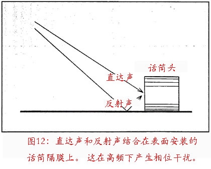
当直达声和å射声在振膜ä¸å¿ƒç‚¹è¿›è¡Œèžåˆæ—¶ï¼Œä¼šåœ¨é«˜é¢‘部分出现相ä½å¹²æ¶‰çŽ°è±¡ã€‚振膜尺寸越å°ï¼Œå»¶æ—¶ä¹Ÿè¶Šå°ï¼Œå¹¶ä¸”产生最大抵消的频率越高。如果振膜直径为1 cm或更å°æ—¶ï¼Œäº§ç”Ÿæœ€å¤§æŠµæ¶ˆçš„频率就会出现在å¯é—»é¢‘è°±ä¹‹ä¸Šï¼Œå› æ¤é‡‡ç”¨è¿™ç§ç»“构设计的界é¢ä¼ 声器在高频部分的频å“曲线相对æ¥è¯´è¾ƒä¸ºå¹³å¦ã€‚
在其他使用æ¡ä»¶ç›¸åŒçš„情况下,å°å°ºå¯¸ä¼ 声器在被水平放置在平é¢ä¸Šæ—¶ï¼Œç›¸è¾ƒäºŽå¤§å°ºå¯¸ä¼ 声器所产生的高频滚é™å¹…度较å°ã€‚
å½“ä¼ å£°å™¨è¢«å‘下指å‘安装时(æ¢èƒ½å™¨æŒ‡å‘åå°„å¹³é¢ï¼‰ï¼Œä¼šåœ¨æŒ¯è†œå’Œå¹³é¢ä¹‹é—´å½¢æˆä¸€ä¸ªç»†ç¼å’Œå¤åˆè…”体。这个细ç¼å’Œè…”体在声å¦ä¸Šä¼šæž„æˆä¸€ä¸ªRLC网络(低频滤波器),导致在高频部分出现滚é™çŽ°è±¡ã€‚ä¼ å£°å™¨å°ºå¯¸è¶Šå°ï¼Œå£°å¦è…”体越å°ã€ç»†ç¼è¶ŠçŸï¼Œå› æ¤åœ¨å¯é—»é¢‘段内的高频滚é™å¹…度也越å°ã€‚
在作为界é¢ä¼ å£°å™¨ä½¿ç”¨æ—¶ï¼Œå¾®åž‹ä¼ å£°å™¨åœ¨é«˜é¢‘åŒºåŸŸçš„æŒ‡å‘ç‰¹æ€§çš„ä¸€è‡´æ€§ä¼˜äºŽå¤§å°ºå¯¸ä¼ å£°å™¨ã€‚å¯¹äºŽå¤§å°ºå¯¸ä¼ å£°å™¨æ¥è¯´ï¼Œç”±äºŽç•Œé¢å射产生的相ä½æŠµæ¶ˆå‘生在å¯é—»é¢‘段内,åŒæ—¶è¿™ç§ç›¸ä½å¹²æ¶‰ä¹Ÿä¼šå½±å“指å‘特性。
å¾®åž‹ä¼ å£°å™¨çš„ç¼ºç‚¹
微型指å‘æ€§ä¼ å£°å™¨ä¼šåœ¨ä½Žé¢‘åŒºåŸŸå‡ºçŽ°æ»šé™çŽ°è±¡ï¼Œä¸»è¦æ˜¯ç”±äºŽå¯¹äºŽå°å°ºå¯¸æ¢èƒ½å™¨æ¥è¯´éœ€è¦è¾ƒä½Žçš„振膜震动阻尼æ¥èŽ·å¾—åˆé€‚çš„çµæ•åº¦ã€‚但这个问题å¯ä»¥é€šè¿‡åœ¨ä¼ å£°å™¨ç”µæ°”éƒ¨åˆ†åŠ å…¥æ ¡æ£å‡è¡¡ï¼ˆæå‡ä½Žé¢‘)或借助近讲效应æ¥èŽ·å¾—更平滑的频å“æ›²çº¿ã€‚å› æ¤ï¼Œå¯¹äºŽè¿‘è·ç¦»æ‹¾éŸ³çš„ä¹å™¨æ¥è¯´ï¼Œä½Žé¢‘部分的声音信å·èƒ½å¤Ÿè¢«å¿ 实地还原。
ä¼ å£°å™¨çš„çµæ•åº¦ä¸ŽæŒ¯è†œé¢ç§¯æˆæ£æ¯”ã€‚å› æ¤ï¼Œç›¸å¯¹æ¥è¯´å°å°ºå¯¸æ¢èƒ½å™¨çš„信噪比低于大尺寸æ¢èƒ½å™¨ã€‚å°å°ºå¯¸æ¢èƒ½å™¨çš„ç‰æ•ˆå™ªéŸ³é€šå¸¸ä¸º28 – 33 dBA,大尺寸æ¢èƒ½å™¨çš„ç‰æ•ˆå™ªå£°é€šå¸¸ä¸º14 – 18 dBA。
在实际应用当ä¸ï¼Œå¾®åž‹ä¼ 声器较低的信噪比并ä¸ä¼šäº§ç”Ÿæ˜Žæ˜¾çš„问题。安装è·ç¦»éžå¸¸è¿‘çš„å¾®åž‹ä¼ å£°å™¨ä¼šä»Žä¹å™¨æŽ¥æ”¶éžå¸¸é«˜çš„è¾“å…¥å£°åŽ‹ï¼Œå› æ¤èƒ½å¤Ÿæœ‰æ•ˆæ高拾å–ä¿¡å·çš„信噪比。å¦ä¸€ä¸ªåŠžæ³•æ˜¯å°†æ¢èƒ½å™¨å®‰è£…在åå°„ç•Œé¢ï¼Œç›´è¾¾å£°ä¸Žå射声的耦åˆå åŠ ä¼šæä¾›é¢å¤–çš„6 dB输入声压。æ¢å¥è¯è¯´ï¼Œè¡¨é¢å®‰è£…æ–¹å¼å¯ä»¥æœ‰æ•ˆçš„将信噪比æ高6 dB。
åœ¨è‡ªç”±åœºä¼ å£°å™¨å’Œç•Œé¢ä¼ 声器之间选择
è‡ªç”±åœºä¼ å£°å™¨é€šå¸¸ç”¨äºŽè¿œç¦»åå°„é¢çš„ä½ç½®ï¼Œç•Œé¢ä¼ 声器则用于诸如地æ¿ã€å¢™é¢ã€æ¡Œé¢ã€é’¢ç´ç›–或内部平é¢ç‰ä½ç½®ã€‚这些界é¢ä¼ 声器通常是一个紧邻声åå°„æ¿æˆ–ç•Œé¢ã€é¢å‘下方的微型电容æ¢èƒ½å™¨æˆ–é¢å‘上方嵌装在一个声åå°„æ¿æˆ–ç•Œé¢ä¸Šçš„微型电容æ¢èƒ½å™¨ã€‚ä¼ å£°å™¨æŒ¯è†œæŽ¥æ”¶åˆ°çš„ç›´è¾¾å£°å’Œå射声在所有频率都是åŒç›¸çš„ï¼Œå› æ¤ä¸ä¼šäº§ç”Ÿç›¸ä½å¹²æ¶‰çŽ°è±¡ã€‚
在录音室里,界é¢ä¼ 声器通常被贴在钢ç´ç›–下方使用,或者贴在墙å£ä¸Šæ‹¾å–房间的环境声。界é¢ä¼ 声器å¯å®‰è£…在ä¹å™¨ä¹‹é—´çš„硬质障æ¿æˆ–å¹³æ¿ä¸Šï¼Œå°†å…¶ä½œä¸ºå®šå‘æ‹¾éŸ³ä¼ å£°å™¨ä½¿ç”¨ã€‚
采用å•ä¸€æŒ‡å‘设计的界é¢ä¼ 声器éžå¸¸é€‚åˆç”¨äºŽæ¼”讲ã€æ–°é—»æ’报ã€æˆå‰§æˆ–音ä¹å‰§è¡¨æ¼”ä¸å¯¹èˆžå°åœ°é¢ä¿¡å·çš„拾å–。
å½“ä¼ å£°å™¨å®‰è£…ä½ç½®è¿œç¦»åå°„é¢æ—¶ï¼Œåº”é€‰ç”¨è‡ªç”±åœºä¼ å£°å™¨ã€‚å½“ä¼ å£°å™¨ä¸Žå£°æºä¹‹é—´çš„è·ç¦»éžå¸¸è¿‘的时候,也å¯ä»¥ä½¿ç”¨è‡ªç”±åœºä¼ 声器。æ¤æ—¶ï¼Œç›¸è¾ƒäºŽç›´è¾¾å£°ï¼Œå射声的能é‡è¾ƒå¼±ã€‚å½“ä¼ å£°å™¨å®‰è£…ä½ç½®è·ç¦»åå°„é¢è¾ƒè¿‘时,应选用界é¢ä¼ 声器。
ç•Œé¢ä¼ 声器具有以下优点:
ï‚ ç”±äºŽç›´è¾¾å£°ä¸Žå射声的èžåˆï¼Œå£°å¦çµæ•åº¦å’Œä¿¡å™ªæ¯”éƒ½ä¼šå¢žåŠ 6 dB
ï‚ èƒ½å¤Ÿæœ‰æ•ˆæ¶ˆé™¤ç”±äºŽåå°„é€ æˆçš„æ¢³å¦†æ»¤æ³¢çŽ°è±¡ï‚ å¯ä½¿ç”¨å¤šä¸ªåå°„å¹³é¢æ¥å¢žåŠ 信噪比(æ¯ä¸€ä¸ªå¹³é¢å¯å¢žåŠ 6 dB)和å‡å°‘æ··å“声的拾å–(æ¯ä¸€ä¸ªå¹³é¢å¯é™ä½Ž3 dB)
ï‚ ç¦»è½´åŒºåŸŸå£°æŸ“è‰²æœ€å°åŒ–(对于宽角度拾音或æŒç»ç§»åŠ¨çš„声æºæ¥è¯´ï¼‰
ï‚ ç”±äºŽæ··å“å£°é€ æˆçš„声染色最å°åŒ–ï‚ å…·å¤‡å‡ºè‰²çš„â€œå»¶å±•â€ç‰¹æ€§â€“ å¯æ¸…晰地拾å–è·ç¦»è¾ƒè¿œçš„å°èƒ½é‡å£°æºä¿¡å·ï‚ è¿™ç±»åž‹ä¼ å£°å™¨é€šå¸¸å¹¶ä¸æ˜¾çœ¼ï¼Œå¯ä»¥ç¼“è§£â€œä¼ å£°å™¨æ惧症â€
ç•Œé¢ä¼ 声器的缺点:
ï‚ ä¼ å£°å™¨å¿…é¡»æ”¾ç½®åœ¨è·ç¦»å£°æºç›¸å¯¹è¾ƒè¿œçš„ä½ç½®ï¼Œå¹¶ä¸”å¯èƒ½ä¼šæ‹¾å–到过多与声æºæ— 关的声音ã€æ··å“声或出现声åé¦ˆï‚ éœ€è¦ä¸€ä¸ªå°ºå¯¸è¾ƒå¤§ã€ç¬¨é‡çš„ç•Œé¢æ¥æ‰©å±•ä½Žé¢‘å“应和实现对低频的定å‘拾å–
ä¸åŒä»·æ ¼ä¹‹é—´çš„选择
åœ¨é€‰æ‹©ä¼ å£°å™¨çš„æ—¶å€™ï¼Œæˆæœ¬æ˜¯å…¶ä¸ä¸€ä¸ªè€ƒè™‘å› ç´ ï¼Œç‰¹åˆ«æ˜¯å¯¹äºŽé¢„ç®—è¾ƒä¸ºç´§å¼ çš„å®¶åºå·¥ä½œå®¤æ¥è¯´ã€‚
é«˜ç«¯ä¼ å£°å™¨ä»·æ ¼æ›´é«˜çš„åŽŸå› ï¼š
ï‚ å“è´¨æŽ§åˆ¶æ›´ä¸ºä¸¥æ ¼ï¼Œå› æ¤å…¶å®¹å·®èŒƒå›´è¾ƒå°ã€‚å“æŽ§ä¸¥æ ¼çš„å¥½å¤„æ˜¯ï¼Œæ¯ä¸€æ”¯ä¼ 声器的å“è´¨ä¸€è‡´æ€§æ›´å¥½ã€‚åˆ¶é€ å•†å¯¹çµæ•åº¦ã€é¢‘率å“应和指å‘特性进行细致的控制也就æ„味ç€åˆ¶é€ æˆæœ¬ä¼šå¢žåŠ ,当然售价也会éšä¹‹æé«˜ï‚ æ供一些é¢å¤–çš„é™„åŠ å±žæ€§ã€‚ä¾‹å¦‚ï¼ŒåŒçº¿åœˆã€å†…置防震架ã€æŒ‡å‘性å¯è°ƒã€é¢‘å“曲线å¯è°ƒã€å¼€å…³ã€å†…置衰å‡å™¨ã€å¯æ›¿æ¢çš„组件ã€multiple-D结构ã€æ˜‚贵的高通é‡ç£ä½“ã€åšå›ºçš„结构设计和使频率å“应更平滑的å¤æ‚的声å¦æ ¡æ£ç½‘络
结论
我们都知é“æ²¡æœ‰ä¸€æ”¯ä¼ å£°å™¨èƒ½å¤Ÿé€‚ç”¨äºŽæ‰€æœ‰åº”ç”¨åœºåˆã€‚å¦‚æžœä¸€æ”¯ä¼ å£°å™¨åœ¨æŸä¸€é¢†åŸŸç‰¹åˆ«å‡ºè‰²çš„è¯ï¼Œé‚£ä¹ˆå¾ˆæœ‰å¯èƒ½å®ƒåœ¨å…¶ä»–åº”ç”¨é¢†åŸŸçš„é€‚ç”¨æ€§æ¯”è¾ƒå·®ã€‚é€‰æ‹©ä»€ä¹ˆæ ·çš„ä¼ å£°å™¨å¾ˆå¤§ç¨‹åº¦ä¸Šå–å†³äºŽä½ æ„¿æ„åšå‡ºå¤šå°‘妥åã€‚é€šè¿‡äº†è§£ä¼ å£°å™¨çš„å·¥ä½œåŽŸç†ï¼Œå¯ä»¥å¸®åŠ©æˆ‘们åšå‡ºæ›´æ˜Žæ™ºçš„选择。
有时,会有一支在设计上完全没有任何折衷妥åçš„ä¼ å£°å™¨å‡ºçŽ°ã€‚ä¹Ÿå°±æ˜¯è¯´ï¼Œè¿™ä¸ªæ–°å‡ºçŽ°çš„ä¼ å£°å™¨å¯èƒ½ä¼šåœ¨èŽ·å¾—æŸé¡¹æ€§èƒ½æå‡çš„åŒæ—¶è€Œæ— 需å‘之å‰é‚£æ ·åœ¨å…¶ä»–æ–¹é¢åšå‡ºç‰ºç‰²ã€‚è¿™ç§æƒ…况通常是在工程å¦å‡ºçŽ°çªç ´çš„时候æ‰ä¼šå‘生。
ä¾‹å¦‚ï¼Œç”µå®¹ä¼ å£°å™¨æ›¾ç»è¢«è®¤ä¸ºæ˜¯åªèƒ½åœ¨å½•éŸ³å®¤å®‰å…¨ä½¿ç”¨çš„专用设备,而现在已ç»å‡ºçŽ°äº†å¤§é‡èƒ½å¤Ÿæ‰¿å—多次跌è½åœ¨ç¡¬è´¨æœ¨åœ°æ¿è¿™ç§æ„å¤–æƒ…å†µçš„å½•éŸ³å®¤çº§åˆ«ç”µå®¹ä¼ å£°å™¨ã€‚åŒæ ·ï¼ŒåŠ¨åœˆä¼ 声器在过去所能æ供的çµæ•åº¦è¿œè¿œä½ŽäºŽç”µå®¹ä¼ 声器,而现在由于ç£ä½“æ质和ç£ä½“结构的改进,市场上已ç»å‡ºçŽ°äº†é«˜çµæ•åº¦çš„åŠ¨åœˆä¼ å£°å™¨ã€‚
å› æ¤ï¼Œå°½ç®¡åœ¨è®¾è®¡ä¸Šåšå‡ºæŠ˜è¡·ä»ç„¶æ˜¯æ— 法改å˜çš„äº‹å®žï¼Œä½†åˆ¶é€ å•†ä»¬éƒ½åœ¨åŠªåŠ›æœ€å°åŒ–æŠ˜è¡·å’Œåˆ¶é€ æ›´å¥½çš„ä¼ å£°å™¨ã€‚å› æ¤ï¼Œé€‰æ‹©åˆé€‚çš„ä¼ å£°å™¨ä¼šå˜å¾—越æ¥è¶Šå®¹æ˜“。
作者: Bruce Bartlett 翻译:易科国际金磊
Smart Bms,Bms For Battery,Bms For Lithium Battery,Bms Module
HuiZhou Superpower Technology Co.,Ltd. , https://www.spchargers.com