Before the computer appeared, in order to connect serial devices, EIA developed the RS232 standard. After the PC appeared, the existing serial device became a PC peripheral, naturally adopting the RS232 standard.
At present, the serial communication interface of the PC adopts the EIA-RS-232C standard, and C represents the latest modification in 1969. The EIA-RS-232C standard specifies electrical characteristics, logic levels, and various signal line functions. The EIA-RS-232C standard uses positive and negative voltages to indicate the logic state. If the voltage is between -3V and -15V on the data signal line, it indicates logic 1. If the voltage is between +3V and +15V, it indicates logic 0. If the voltage is between -3V and -15V on the signal line, it means the off state. If the voltage is between +3V and +15V, it means the on state. Voltages between -3V and +3V and below -15V and above +15V are meaningless.
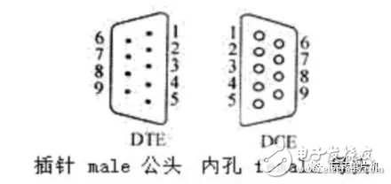
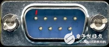
The CPU and the terminal use TTL level and positive logic. The TTL level uses +5V to indicate logic 1, and 0V to indicate logic 0. They are not compatible with the level and negative logic used by EIA and need to be converted in the interface circuit. The EIA-RS-232C standard does not define the physical characteristics of the connector. Therefore, various types of connectors of DB-25, DB-15 and DB-9 have appeared, and the COM1 and COM2 serial interfaces of the PC adopt the DB-9 connector . The ELA-RS-232C standard specifies that when the bit error rate is less than 4%, the wire length is allowed to be 15m. In practical applications, when 9600 b/s or ordinary twisted pair shielded wires are used, the transmission distance can reach 30m to 35m. The DB-9 connector of the COM1 and COM2 serial interfaces of the PC is a male (pin) header that provides nine pins for asynchronous communication . They are: 1 pin (DCD) data carrier detection, 2 pin (RXD) receive data, 3 pin (TXD) transmit data, 4 pin (DTR) data terminal preparation, 5 pin (SG) signal ground, 6 pin (DSR) The data device is ready, 7-pin (RaS) request to send, 8-pin (CTS) clear to send, 9-pin (RI) ringing indication. The order of the DB-9 male (needle) head is as shown in the figure below. The order of the DB-9 female (hole) head is as shown in the figure below. Pay special attention to the male pin number from sitting to right and the female head from right to left . In the EIA-RS-232C standard, there are three transmit signals: TXD, RTS, and DTR, typical output current for each line.
It is ±8mA/±12V. Typically powered by RTS and DTR, it provides approximately 192mW of power. 
The PC end is generally male, as shown

In combination with the above description, if the Modem is not involved. The serial port transmission data can be realized as long as there is a receiving data terminal 2 pin and a transmitting data terminal 3 pin. The receiving data end of one device should be connected to the transmitting data end of another device. That is, the reception and transmission cross each other, and the signals are correspondingly connected.
Question 1: When do you use crossover and when do you use direct connection? Standard serial port pin 2 is RX, pin 3 is TX, (ie, the pin 9 of the 9-pin serial port is connected to the RXD pin of the main control chip, and the pin 3 is connected to the TXD pin of the main control chip) If the serial port of the MCU development board and the serial port of the computer are both standard serial ports, the two serial ports should be connected by cross lines. However, in real life, there are many direct connections (probably the direct connection is not complicated to cross the line). In order to match the use of the direct connection, connect the RXD pin of the main control chip to the 3 pin of the serial port when drawing the board. The TXD pin of the main control chip is connected to the 2 pin of the serial port, so the serial port on the development board is not the standard serial port, that is, 2 becomes TX, 3 becomes RX, and of course, a direct connection should be used when connecting with a standard serial port. It is. Look at the serial port on a development board is a standard serial port or a non-standard serial port, it is still necessary to see how the schematic is connected!
In general: RS232 DB-9 interface connection line includes three types: male to female, male to male, female to female. All three types of connecting lines have cross lines and straight lines, so there are a total of 6 connections.
Question 2: How to identify the cross serial cable and the direct serial cable? Use a multimeter to measure, if 2 and 2 pass, 3 and 3 pass are direct serial cable; if 2 and 3 pass, 3 and 2 pass are cross serial cable. Some people are confused that the outside of the mother's mouth is an insulating rubber. How can the probe of the multimeter not be inserted? Then cut a small piece of solder wire (I have also considered using wire, but the wire is too thin, we can not guarantee that it can be in good contact with the metal part of the female mouth, the solder wire is thicker, it can be with the metal inside the mother Good contact), then test the multimeter probe to the solder wire. Of course, if you get a serial cable every time you have to use a multimeter to test whether it is directly connected or cross-over, it is not very troublesome. It is a good way to teach you a good way to distinguish, that is: the two female mouths are cross One male and one female is directly connected . (The serial port lines at both ends are public).
The KSPOWER brand AU plug fixed adapters is one black or white color constant voltage mode, accepts universal input 100-240V AC voltage and provides the complete au plug adaptor solutions covering the dc output voltage ranging from 5volt to 36volt, the output wattages ranging from 5 watts to 60 watts and the output current ranging from 100ma to 6000ma single output australian adapter. The power supply australia follows high quality level VI energy efficiency and meet IEC/EN/UL 62368 safety standards, with RCM SAA C-Tick RoHS safety certificates. The electrical adaptor plugs is Class II power designed with the standard AU AC plug export for Australia market and offers three years after-sale customer service. The dc adaptor plug accepts various dc connector sizes optional for various LED, audio/video and I.T.E applications and protections for short circuit, over load, over voltage and over temperature.
au plug adaptor, power supply australia, electrical adaptor plugs, dc adaptor plug, australian adapter
Shenzhenshi Zhenhuan Electronic Co., Ltd , https://www.szzhpower.com