Why use components to derate? Because if the working state of the component does not exceed the specifications on the specifications provided by the supplier. Then you can achieve full life work. Derating can improve the reliability of the product.
The derating rules were developed based on the worst case. Components that work in the worst conditions are an important factor in achieving a life expectancy that does not reach the rated life.
The worst case condition is the working condition in which the component is subjected to the maximum stress during operation. This situation is generally a combination of one or more of the parameters of the external environment such as temperature, voltage, number of switches, load, and the like. The boundary conditions for these stresses are generally given in the specification of the component.
A good design is to evaluate the reliability of the design based on the design risk of the component under worst-case conditions. The risk assessment can also determine the cause of the failure, the potential risk, the probability of failure, the severity of the consequences, and so on.
To develop a derating specification, a failure risk assessment under the worst case is performed. To conduct a risk assessment, an accelerated experimental model is established. If the risk assessment is done according to normal usage time, the market share is already divided after the evaluation is completed.
The accuracy of the model will seriously affect the outcome of the risk assessment. To accurately guarantee the accuracy of the model, it was asked by a university. In our case, let's take a brief analysis of qualitative.
Acceleration factors for accelerated testing generally follow Arrhenius's law:
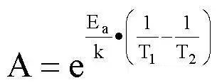
among them:
A acceleration factor
Ea activation energy
K Boltzmann constant, 8.63E-5 eV/K
T absolute temperature
If the acceleration factor corresponds to a value under a certain derating condition, then the following formula can be used to calculate the life in other cases:
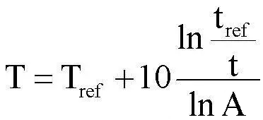
among them:
T temperature in degrees Celsius
Tref reference derating temperature in degrees Celsius
Tref reference service life, unit KHrs (thousand hours)
t service life, unit KHrs (thousand hours)
A acceleration factor every 10 degrees Celsius
For example, if a component has a lifetime of 30KHrs at 90 degrees Celsius and an acceleration factor of about 2 per 10 degrees Celsius, at what temperature does the component's lifetime become 20KHrs?

Because of the complexity and confidentiality of integrated circuits, we can only infer the reliability of integrated circuits based on the junction temperature of the semiconductor.
We usually specify:
1, the maximum working voltage, does not exceed the rated voltage of 80%
2, the maximum output current, does not exceed the rated current of 75%
3, junction temperature, maximum 85 degrees Celsius, or not exceeding 80% of the rated maximum junction temperature
Second, the diodeDiodes come in a wide variety of features and characteristics. Therefore, there are general requirements and special requirements:
common enquiries:
Long-term reverse voltage <70% to 90% × VRRM (maximum repeatable reverse voltage)
Maximum peak reverse voltage <90% × VRRM
Forward average current <70%~90%×rated value
Forward peak current <75% to 85% × IFRM forward repeatable peak current
For operating junction temperatures, different diode requirements are slightly different:
Signal diode < 85 ~ 150 ° C
Glass passivated diode < 85 ~ 150 ° C
Rectifier Diode and Fast Recovery, Ultra Fast Recovery Diode (<1000V) <85~125°C
Rectifier diode and fast recovery, ultra fast recovery diode (≥1000V) <85~115°C
Schottky diode < 85 ~ 115 ° C
Zener diode (<0.5W)<85~125°C
Zener diode (≥0.5W)<85~100°C
Tcase (case temperature) ≤ 0.8 × Tjmax - 2 × θjc × P, 2 × θjc × P < 15 ° C, θjc is the thermal resistance from the junction to the shell, and P is the power loss. This is an empirical value for reference.
Many of the indicators here give a range because there is a contradiction between different reliability requirements and costs. So give a relatively more attention to reliability and a cost-oriented two values ​​for reference. The same is true below.
Third, power MOSVGS<85%×VGSmax (maximum gate drive voltage)
ID_peak<80%×ID_M (maximum drain pulse current)
VDS<80~90%×rated voltage
dV/dt<50%~90%×rated value
Junction temperature <85°C~80%×Tjmax (maximum working junction temperature)
Tcase (case temperature) ≤ 0.8 × Tjmax - 2 × θjc × P, 2 × θjc × P < 15 ° C, θjc is the thermal resistance from the junction to the shell, and P is the power loss. This is an empirical value for reference.
Four, triodeAll voltage specifications are limited to 85% of the rated value
Power loss does not exceed 70% to 90% of rated value
The IC must be derated by 30% within the RBSOA (Reverse Bias Safe Work Area) and FBSOA (Positive Partial Safety Work Area) (ie 70% of the rating)
Junction temperature does not exceed 85 ~ 125 ° C
Tcase (case temperature) ≤ 0.75 × Tjmax - 2 × θjc × P, 2 × θjc × P < 15 ° C, θjc is the thermal resistance from the junction to the shell, and P is the power loss. This is an empirical value for reference.
Five, electrolytic capacitorAluminum electrolytic capacitors are a very important component in switching power supplies. The failure rate of many switching power supplies is high because of the improper use of aluminum electrolysis. Due to the importance of aluminum electrolysis, we have more research on him, so there are more rules.
1, Vdc + Vripple <90% × rated voltage
2, under the capacitor body, the front of the PCB, try not to have other traces outside the ground.
3, ripple current, this problem is more complicated, because the spectrum of the ripple current in the switching power supply is very rich, so the ripple current must be converted:
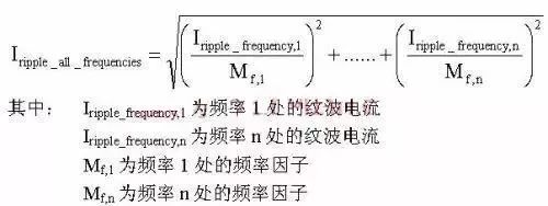
The frequency factor that the supplier should be able to provide.
The ripple current must be within 70% to 90% of the supplier's rating.
4, the initial capacity of the electrolytic capacitor to ensure a 20% margin. At the same time, an additional 20% capacity margin is required to cope with the capacity decay as soon as the life is reached.
5, the life cycle of the electrolytic capacitor temperature acceleration factor is 2 every 10 ° C, that is, for every 10 degrees increase in temperature, the life is halved.
6, shell temperature Tcase is limited by the design life.
7, since the temperature rise <5 ° C, the so-called self-temperature rise, refers to the temperature rise caused by the self-heating of the capacitor when actually working.
Six, ceramic capacitorOperating voltage <60% to 90% × rated voltage
Surface temperature <105 ° C
Self-temperature rise <15 ° C or defined by the specification, whichever is lower.
Seven, film capacitor1, in the switching power supply, do not use polystyrene capacitors, because polystyrene capacitors are relatively poor heat resistance.
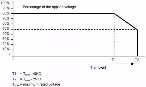
2, surface temperature <85 ° C, over 85 ° C withstand voltage according to the following figure derating. The voltage here refers to the DC voltage superimposed on the AC peak voltage.
3, polyester capacitor self-temperature rise <8 ° C or defined by the specification, whichever is lower
4, polypropylene capacitor self-temperature rise <5 ° C or defined by the specification, whichever is lower
5, the life of the film capacitor depends on the voltage value and the rate of rise of the voltage pulse. The relationship between the number of pulses allowed and the voltage value and the slope of the pulse is as follows:
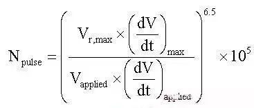
among them:
Npulse is the total number of pulses
Vr, max maximum rated DC voltage
Vapplied actually uses peak-to-peak voltage
(dv/dt)max maximum rated pulse slope
(dv/dt) applied actually uses the pulse slope
Eight, resistanceResistance can be divided into three categories: fixed linear resistance, fixed nonlinear resistance, variable resistance
Fixed linear resistors include: carbon film, metal film, metal oxide film, metal glaze, carbon and other resistance and winding resistance.
Fixed nonlinear resistors include: NTC, PTC
The reliability of the resistor is mainly determined by the temperature of the resistor, and the temperature is the effect of the superposition of the ambient temperature and the self-power loss.
Both power and voltage impose limitations on the choice and use of resistors:
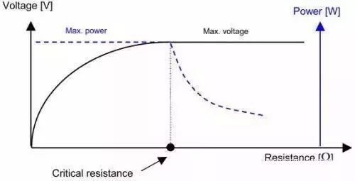
As can be seen from the figure, for resistors whose resistance is lower than the critical resistance, the use is limited by power, and for resistors higher than the critical resistance, the use is limited by withstand voltage.
The power limit for a single pulse depends on the shape of the pulse. At the same time, the peak voltage of the pulse must not exceed the rated limit.
Derating of resistors using rules:
1, using metal glaze resistors in circuits with transient high voltage pulses
2, use a wirewound resistor in the case of large inrush current
3, continuous power <50% × rated power
4, do not use >1MΩ carbon film resistor, because long-term stability is too bad
5, high resistance, long-term stability, good resistance should use metal glaze resistor
6, after the thermal shock test, the resistance of the resistance must be within ± 5% of the rated range
7, fusible resistors, such as fuse resistors, do not rely too close to the PCB to avoid overheating the PCB
8, try not to use rectangular chip resistors in the ESD protection circuit, because the sharp corners of the rectangle are easy to discharge
9, in the voltage and current sampling, if using chip resistors, try to use the size above 1206.
10, pressure drop derating use:
For carbon film, metal film, metal oxide film resistance:
When R>100K, VRMS<50%×rated maximum continuous working voltage
When R≤100K, VRMS<90%×rated maximum continuous working voltage or 90%×(P×R)0.5, whichever is lower.
For carbon resistors, glaze resistors and wirewound resistors:
VRMS < 90% × rated maximum continuous operating voltage or 90% × (P × R) 0.5, whichever is lower.
11. The instantaneous power when there is an inrush current in the circuit can be calculated according to the following empirical formula:
P = I2 × R × t / 4, where t is the time when the current drops to a maximum of 38%.
Nine, magnetic componentsIn magnetic components, the maximum voltage between the paired wires cannot exceed the following table:
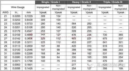
The AWG wire gauge can be converted to mm unit wire diameter according to this formula:
d=25.4×0.005×92 ((36-AWG)/39)
The enameled wire has a lifespan acceleration factor of approximately 2.5 per 10 °C.
The temperature derating of the line package states:
CLASS B: 95 ° C ~ 110 ° C Note: The rated temperature is 130 ° C
CLASS F: 110 ° C ~ 125 ° C Note: The rated temperature is 155 ° C
CLASS H: 125 ° C ~ 150 ° C Note: The rated temperature is 180 ° C
Core derating requirements:
Bmax < 80% × Bsat under any conditions.
Bsat is the saturation magnetic induction of the core
TCORE<70%×Tcurie-10°C
Tcurie is the core Curie point temperature
Ten, metal oxide varistor MOVTcase ≤ 85 ° C under any conditions
The specific selection is recommended as:
150Vrms for AC120V/127V
AC220V selects 275Vrms (this is still controversial)
AC277V selects 320Vrms
AC347V selects 420Vrms
Eleven, printed circuit boardThe PCB material and the highest available surface temperature are as follows:
FR2 75°C
FR3 90°C
FR4 125°C
CEM1 125°C
CEM3 125°C
In addition, there are some rules:
You can use vias to help dissipate heat
The current flowing through each via does not exceed 2A
The relationship between the spacing between the wiring and the voltage refers to UL935
FR1 has twice the thermal conductivity of FR4, but FR1 is not suitable for double panels.
Twelve, fuseThe derating of the fuse is a compromise between circuit protection reliability and fuse life.
Derating the fuses does not directly lead to an increase in product reliability.
Ambient temperature and current are the main factors affecting the life of the fuse.
At 25 ° C, the fuse current should be derated by 25%. When the ambient temperature rises, the slow-blow fuse should be derated by 0.5%/°C. The fast-blow fuses are derated by 0.1%/°C.
Thirteen, optocouplerMaximum working voltage <70%~90%×rated voltage
Maximum operating current <25% to 90% × rated current
Current transfer ratio, 20% margin based on product life time
Junction temperature <85 °C ~ 100 °C
Box Header Connector,High Temperature Resistant Box Header Connector,Gold-Plated Box Header Connector,Plastic Box Header Connector
Shenzhen Jinyicheng Electronci Technology Co.,Ltd. , https://www.jycconnector.com