Many applications, such as magnetic field induction, calibration, and scientific experiments, often use high frequency Helmholtz coils to produce a uniform but time varying high frequency magnetic field. Generating such a magnetic field requires the use of a high frequency Helmholtz coil driver. Since the magnetic field density is proportional to the current, in order to generate a large magnetic field, it is necessary to generate a large current. However, the coil impedance also becomes high impedance at high frequencies.
For a given driver voltage amplitude, the coil current is inversely proportional to the coil impedance. So the two opposite factors that affect the magnetic field are current and frequency. It is very difficult to achieve a high frequency magnetic field. This article discusses three techniques that help high-frequency Helmholtz coils generate strong magnetic fields.
High frequency Helmholtz coil foundation
The Helmholtz coil is named after the German physicist Hermann von Helmholtz. It consists of two identically placed electromagnetic coils placed in parallel. The two coils are centered on the same axis, just like a mirror image, as shown in Figure 1. Show. When the current passes through the two high-frequency Helmholtz coils in the same direction, a highly uniform magnetic field is generated in the three-dimensional space inside the coil. These Helmholtz coils are often used to offset background (earth) magnetic fields, measurements and calibration, and magnetic fields in electronic device sensitivity tests.
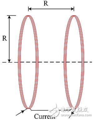
Figure 1: A single-axis high-frequency Helmholtz coil consists of a pair of two coils of radius R and spacing equal to R.
Design and manufacture of Helmholtz coils
The high frequency Helmholtz coil is constructed from two coils. Since the two magnetic coils are designed to be identical, a uniform magnetic field is produced when the coil radius is equal to the separation distance. The two coils are connected together in series, so the currents fed to them are the same, resulting in two identical magnetic fields. The superposition of these two magnetic fields produces a uniform magnetic field in the cylindrical space at the center of the two parallel coils.
The uniform magnetic field of this cylindrical space is approximately equal to 25% of the coil radius (R) and the length is equal to 50% of the spacing between the two coils. The high frequency Helmholtz coil can be made into 1, 2 or 3 axes. The multi-axis magnetic coil can generate a magnetic field in any direction in the three-dimensional space inside the Helmholtz coil. The most common high frequency Helmholtz coils are round. Square Helmholtz coils are also frequently used.
Helmholtz's magnetic field calculation
Each Helmholtz coil is made of an electric (copper) wire loop. A magnetic field is generated when current passes through it. The magnetic field density is proportional to the current. The Helmholtz coil magnetic field formula is as follows:

B = the magnetic field in Tesla
n = number of turns of the coil
I = current in amps
r = coil radius in meters
It can be seen from Equation 1 that a coil with a smaller radius can produce a higher magnetic field density. The more turns in each coil, the stronger the magnetic field.
High frequency Helmholtz coil model
The Helmholtz magnetic field can be generated by alternating current or by direct current. Most Helmholtz coil applications use static (constant) magnetic fields generated by direct current. Some applications, such as scientific experiments, require high-frequency, non-stationary magnetic fields (kHz to MHz). This article focuses on high frequency Helmholtz coils.

Figure 2: Circuit model of two Helmholtz coils connected in series.
Figure 2 shows a circuit model consisting of a pair of high frequency coils. Each coil can be modeled as a parasitic resistor in series with an ideal inductor. The impedance of the parasitic resistance is generally small. For most high frequency Helmholtz coil applications, this model is sufficient because the test frequency is much lower than the self-resonant frequency.
If the Helmholtz coil is operating at a frequency close enough to its self-resonant frequency, then the circuit model must also contain its parasitic capacitance (CP1 and CP2). The parasitic capacitance is in parallel with each set of inductive resistors in series, as shown in Figure 3.
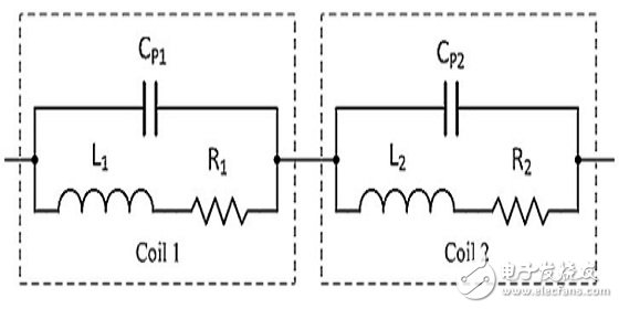
Figure 3: The high frequency Helmholtz coil is modeled as two series connected LCR circuits.
The parasitic capacitance and inductance form a self-resonant frequency. Although the coils are designed to match as closely as possible, some small differences between them may still exist. Each coil has its own series resistance and parasitic capacitance. The parasitic capacitance and the coil inductance form a self-resonant frequency.
High frequency Helmholtz coil connection
High-frequency Helmholtz coils can be connected in series (Figure 2) or in parallel (Figure 4). The series causes the current flowing through the two magnetic coils to be identical. In general, the series can support the maximum current, which can produce the strongest magnetic field. However, since the two coils are connected in series, the total impedance is also doubled. Higher impedances require higher drive amplifier voltages. If the resonance technique described below is used, the impedance can be reduced.
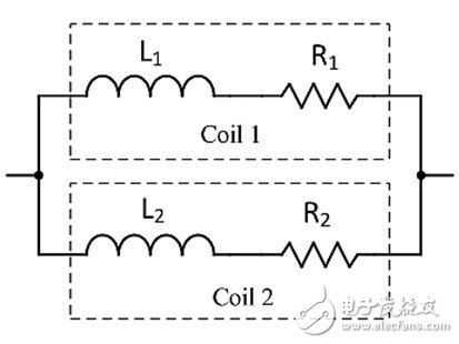
Figure 4: Helmholtz coils in parallel.
The advantage of a parallel Helmholtz coil is that it has a lower impedance. In fact, the impedance is reduced by half, but the current is also reduced by half (the current is divided into two), so the magnetic field is smaller. Parallelism is acceptable if the required magnetic field density is achieved at half the current and low impedance is required, such as in low voltage amplifier drivers. More details on the Helmholtz coil impedance are discussed in the Direct Drive Method section below.
Driving high frequency Helmholtz coil
There are three ways to generate a high frequency alternating magnetic field. The first method is the direct drive method. This method is the easiest way to generate a magnetic field for testing. It is easy to change the frequency and the magnetic field to be measured. The second method is the series resonance method. This is a good way to generate strong magnetic fields and magnetic fields with frequencies up to hundreds of kHz or even MHz. The third method is to use a new current amplification type resonance method. This method produces the highest magnetic field density. Each method will be described in detail below.
Direct drive method
If the experiment is low frequency, or the coil is low inductance, or both conditions are available, then the Helmholtz coil can be directly driven by a waveform amplifier driver (such as the Accel Instruments TS250 waveform amplifier). Due to the low frequency or low inductance, the coil impedance is low enough to be directly driven by the amplifier, as shown in Figures 5 and 6.
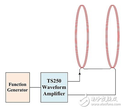
Figure 5: The TS250 waveform amplifier drives a pair of Helmholtz coils.

Figure 6: Circuit diagram of a pair of series Helmholtz coils driven directly by a waveform amplifier.
![]()
I is the peak current
ω is the angular frequency, ω=2πf
L1+L2 is the total inductance,
R1+R2 is the total resistance.
The coil current required to obtain the target magnetic field can be calculated using Equation 1. Then use Equation 2 to calculate the maximum voltage required. Be careful to ignore small parasitic resistance. The maximum voltage occurs when both current and frequency reach their maximum value. The Helmholtz coil can then be driven with a high current and high frequency amplification driver (such as the TS250 function generation amplifier).
Series resonance method
If the generated magnetic field is high frequency, the Helmholtz coil impedance will increase with increasing frequency (Z = jwL). At high frequencies, the coil impedance is high, so high voltages are required to drive large currents through the coil. For example, a 2mH coil impedance at 25kHz is 2512Ω. If you drive this coil with 40V, you will get about 16mA (40V/2512Ω = 16mA). For most applications, this current is not enough to produce a sufficiently strong magnetic field. Strong magnetic field applications require larger coil currents. In order to drive the current of 2A through the coil, a voltage of up to 5024V is required! It is difficult to generate a voltage of 5 kV at 200 kHz.
In order to achieve high current and high frequency electromagnetic fields, it is recommended to use series resonance technology.

Figure 7: The waveform amplifier drives a large current through the Helmholtz coil at the resonance point.
In order to operate the high frequency Helmholtz coil in resonant mode, a series capacitor is required, as shown in Figure 7. The impedance of the series capacitor has the opposite polarity to the inductance. This capacitor acts as an impedance cancellation device that reduces the overall impedance. At resonance, the reactance of the capacitor (the imaginary part of the impedance) completely cancels the reactance of the inductor. This is because the reactance of the inductor and capacitor are equal, but the polarity is reversed.
Therefore only the parasitic resistance of the inductor remains. Since only the resistor is left, the function generation amplifier (TS250) can drive a large current through the Helmholtz coil (LCR circuit) even at high frequencies. This method enables the signal amplifier to drive large currents through the high frequency coil, but it can only operate in a narrow frequency range around the resonant frequency. The downside of resonant technology is that you need to change the capacitance at the same time as you change the frequency.

The series resonant frequency of the Helmholtz coil is given by Equation 3. The series capacitor CS can be calculated using Equation 4. The voltage across the series capacitor can be calculated using Equation 2 above. At high frequencies and high currents, the voltage can reach thousands of volts. For example, when a 2mH high-frequency Helmholtz coil is flowing at 200kHz and 1A, the voltage on the capacitor is 2512V! Therefore, the rating of this capacitor must be at least this voltage.
Note: potential electrical shock
The high current Helmholtz (electromagnetic) coil described above can store enough energy and thus become a shock hazard. Ensure that all electrical connections are insulated from high voltage insulation. The wire must have the above rated voltage rating. Always remember to turn off the waveform amplifier output before connecting or disconnecting the coil and capacitor.
Current amplification resonance
Another type of resonance that is more powerful than series resonance is called current amplifier resonance. This newly invented resonance can boost the Helmholtz coil current by a factor of two. That is, the coil current is twice the current of the source amplifier driver. This resonance therefore magnifies the current and the magnetic field. Detailed information on the resonance of this new invention can be found in the application note "High Frequency Magne TIc Field Generator".
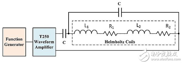
Figure 8: Using the current amplification resonance method, the magnetic field generated by the high-frequency Helmholtz coil can be doubled.
Figure 8 shows a high frequency Helmholtz coil wiring diagram using current amplification resonance. Two capacitors of the same capacity are needed here. A capacitor is connected in series with the coil, which is the same as the series resonance described above. The second resonant capacitor is connected in parallel with the two coils. This shunt capacitance is similar to the parasitic capacitance in the high frequency Helmholtz coil circuit model described above.
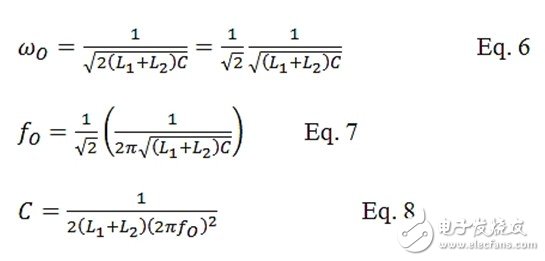
The resonant frequency is expressed by Equation 6. The capacitance of the two capacitors can be calculated using Equation 8. At the resonance point, the Helmholtz coil impedance is resistive, four times the coil parasitic resistance. It is preferable to design a low impedance coil when used in current amplification resonance. Also keep in mind that the magnetic impedance of the magnetic coil is greater than the DC impedance due to the effect of the skin effect.
Summary of this article
This article discusses three methods for driving high frequency Helmholtz coils. The direct drive method is the simplest, but is generally used in low frequency or low inductance applications. Driving a Helmholtz coil using a series resonance method can generate large currents and high frequency magnetic fields. The innovative current-amplified resonance method can even generate a stronger magnetic field at high frequencies.
General Purpose Steel Wire Rope
Aircraft Cable And GP Steel Wire Rope
Widely used in the industry of Port Machinery, Vessels, Elevators, Engineering Machinery, Mining, Petroleum, etc
GAC: 7x7 7x19
GP steel wire rope: 1x7 1x19 6x7 7x7 6x19 7x19 6x12 6x24 6x37
Surface: (1) hot-dip galvanized; (2) electric galvanized; (3) black; (4) PVC coating; (5) stainless steel; (6) zinc + aluminum, etc.
Steel Wire Rope,Galvanized Wire Rope,Galvanized Steel Wire Rope,Galvanized Aircraft Cable
ROYAL RANGE INTERNATIONAL TRADING CO., LTD , https://www.royalrangelgs.com