As more and more mechanical components are replaced by electronic components and the popularity of driver assistance systems, the number of electronic components in automobiles is rapidly increasing. This trend has put more pressure on automakers and their suppliers to find effective ways to protect their electronic components from contamination and seal failure. Ensuring that these electronic components operate reliably over the life of the vehicle is the primary goal, not only to increase cost-effectiveness, but also to promote the brand's high-quality image and reliability.
This article refers to the address: http://
All electronic components, whether compressors, pumps, motors, control units, or sensors of the increasingly popular active safety system, are subject to large temperature fluctuations throughout their life. This occurs when the component housing heats up during vehicle operation and comes into contact with low temperature sputtered water or car wash water on the road surface. This temperature fluctuation creates a significant vacuum effect within the electronics housing. The resulting large differential pressure can severely damage the seals and seals that protect sensitive electronic equipment, causing ingress of dirt particles and liquids, corrosive to electronic components and shortening their useful life. Damaged or defective parts must often be replaced, which increases the warranty and repair costs of the car manufacturer and its suppliers.
Challenges in electronics and batteries in electric vehicles
A major challenge for the automotive industry is temperature management of high-performance electronics and batteries in electric vehicles, because these components need to operate over a range of temperatures for optimum performance. These components become very hot during operation and require liquid cooling. However, this causes a large temperature difference inside the electronic device, and condensation forms at the lowest temperature point on the outer casing, causing corrosion or short circuit. This problem is very common for large battery cases, and if no effective measures are taken to equalize temperature and pressure, this problem is difficult to solve. Due to the size of the outer casing, even a small temperature difference creates sufficient pressure on the outer casing, causing it to deform. In some cases, when the vehicle exits from a higher temperature garage and enters a cold open air environment, a vacuum is created inside the casing, creating a negative pressure of 500 kilograms per square meter. The thin and light casing can hardly withstand such high pressure.
Breathable membrane technology: the balance between air and pressure
Original equipment manufacturers (OEMs) typically have three ways to address this challenge. The first is to potting electronic components. Although this solution results in a perfect sealing system, it also significantly increases the weight of the unit and cannot be reopened for repair in the event of a failure; another method of forming a secure sealing system is the use of high quality seals and thick outer walls. However, the disadvantage of such a system is that it increases component costs and increases unnecessary weight.
A more reasonable common solution is to use a gas permeable membrane that balances the air in the enclosure while also preventing the ingress of liquids and dirt particles.

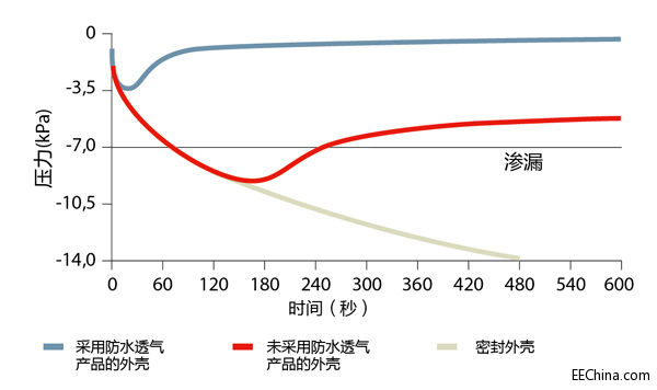
Figure 1 shows the process of continuous accumulation of negative pressure in a closed enclosure. On a casing that is not waterproof and ventilated, after a few rounds of temperature cycling, a pressure of only 7 kPa is sufficient to cause the seal to fail. The outer casing of the waterproof and breathable product balances the pressure and prevents the seal from leaking.
Important characteristics of breathable membrane solutions: air permeability and water permeability
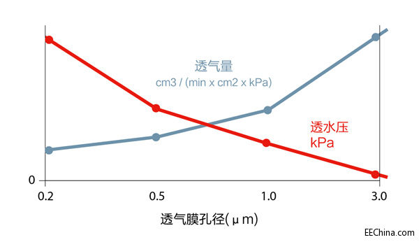
Air permeability and water permeability are two basic parameters that determine the performance of a gas permeable membrane. The amount of air permeability refers to the amount of air passing through the gas permeable membrane at a given time and a given pressure difference. The amount of time required to equalize the differential pressure can be determined by the amount of gas. Permeability refers to the minimum hydrostatic pressure that a gas permeable membrane must withstand before it leaks. These two parameters are also affected by the pore size of the gas permeable membrane, among other factors. The gas permeable membrane supplier must provide a gas permeable membrane with a combination of optimum gas permeability and water permeable pressure parameters for each specific application.
A major challenge for the automotive industry is the increasing size and compactness of electronic components. This means that if the waterproof and breathable components are to be integrated into a smaller enclosure and maximized performance, then the size must be made smaller. This requires that the gas permeability of the surface of the gas permeable membrane is higher per unit area, and the higher the gas permeability, the lower the water permeability, as shown in FIG.

In general, the resistance of the system is determined by its degree of protection (in accordance with DIN 40050-9). The IP test determines the degree of protection of the electronic component housing against solids and liquids. The degree of protection is defined by two numbers: IPXY. The first number (X) indicates the degree of solid foreign body protection, and the second number (Y) indicates the degree of liquid protection. The IPX9K demonstrates the ability to maintain watertightness when a component housing with an integrated gas permeable membrane is exposed to a high pressure water gun.
The IPX9K test was carried out in a test chamber containing an outer casing with a gas permeable membrane exposed to high pressure nozzles at distances of 100 to 150 mm and angles of 0, 30, 60 and 90 degrees. The gas permeability was maintained between 14 and 16 l/min, the water permeability was maintained between 8,000 and 10,000 kPa, and the temperature was maintained at 80 °C.
Chemical resistance of expanded polytetrafluoroethylene (ePTFE) film
Gore uses polytetrafluoroethylene (PTFE) as a gas permeable membrane material, and its unique microstructure makes it particularly suitable for waterproof and breathable applications. The polytetrafluoroethylene (PTFE) raw material is stretched by a specially designed process, and the resulting gas permeable membrane has very small pores, and the nodes in the micropores are connected to each other by fibers. The material thus formed is called expanded polytetrafluoroethylene (or ePTFE), and the low surface tension of the material makes it extremely hydrophobic (water repellency), which means that any water droplets falling on its surface are It is impossible to pass through this gas permeable membrane structure. Such films are also oleophobic (oil resistant) and can repel liquids with low surface tension, such as oil. The oleophobicity of expanded polytetrafluoroethylene (ePPFE) is extremely important for applications in the automotive industry because of the high probability that automotive parts will come into contact with oil, detergent or other automotive fluids.
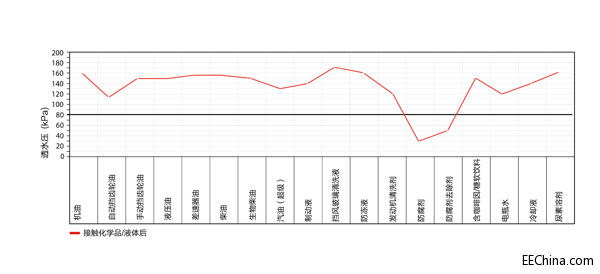
Gore tested its waterproof and breathable solution for up to 20 different chemicals (according to ISO 16750-5). In the test, the waterproof and breathable product was placed in each test liquid and kept at room temperature (21 to 23 ° C) for 24 hours or in an oven for 96 hours. Air permeability and water permeability are measured before and after the test. The results of these two parameters must be within the specified range, as shown in Figure 3.

Test result: The value below the black horizontal line indicates that the corresponding chemical has damaged the gas permeable membrane. Tested for breathable membranes is only limited when infiltrated with preservatives or preservatives, but for all other test chemicals, the test results meet the required standards.
Temperature resistance of ePTFE film
Another advantage of ePTFE is that it is extremely resistant to extreme temperatures. It can withstand temperatures ranging from -150°C to 240°C, a feature that is important for today's trend of reducing engine size while maintaining or even improving performance. Reducing the engine volume in this manner typically causes the temperature to exceed the limit of 125 ° C, which is the limit temperature that current electronic component housings can handle. It is not uncommon for temperatures to reach 150 ° C or higher.
Multimedia Information Box is a new smart box integrated of intelligent line system.It is widely used in connection and allocation of line for home broadband,office broadband,hotel broadband,telephone,computer,television,audio,monitor,switch,power etc.It is mainly used for the unified management and distribution of family weak current signal wiring, including the network, telephone, television, security and other weak current wiring, mainly to avoid the interference of weak current signal by strong electricity, improve the quality of family life.
FTTD Terminal Box,Multimedia Information Box,Optical Splitter Box,Fiber Optic Splitter Box
Chengdu Xinruixin Optical Communication Technology Co.,Ltd , https://www.xrxoptic.com