This article introduces the tutorial diagram of the homemade power amplifier machine, taking you step by step to learn this method, detailed DIY method process of the power amplifier, easy to learn with the combination of graphics and texts. Interested friends come and have a look!
The process of making a self-made amplifier, written in super detailed, the author used a night before and after a week. Although he claims to be only amateurs, there are many places that may not be professional enough, but there are many ideas or practices that can be used for reference. Interested friends may wish to try it out by themselves, because the fun of DIY is in it.
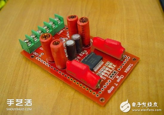
TA2024 finished board purchased on a treasure for 100 yuan
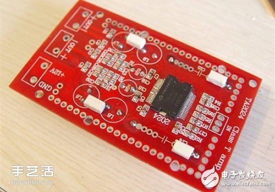
The back of the board is basically a patch component
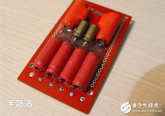
Since the Class T digital power amplifier is an inductively coupled output, two pairs of inductors are essential. But the volume is too large, I removed it and re-sold it to the back and fixed it with hot melt glue. This saves space and allows the front IC to mount a large area of ​​heat sink (in fact, the TA2024 can work without the heat sink, but it feels a little hot when listening.)
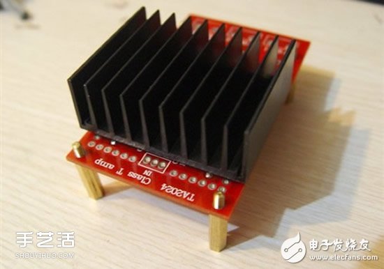
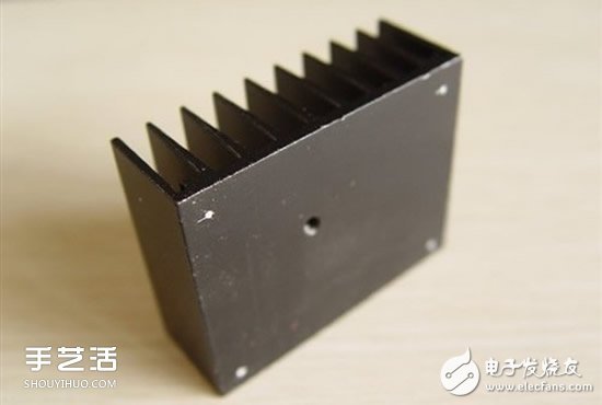
Spend 5 yuan to buy a heat sink, choose the right size
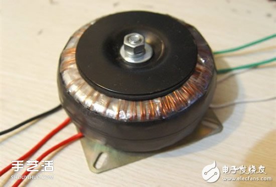
This is also bought for 30 yuan, Φ80 small ring cattle, AC RMS 12V, 35W. Workmanship is OK, of course, copper wire and silicon steel are very common, far from HI-FI by one hundred and eight thousand miles.
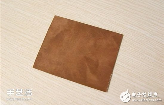
First make a rectification filter board, cut a piece of resin and glass fiber single-sided copper plate that was bought 10 years ago, the surface is oxidized, it does not matter, there are ways to solve. (This kind of board is easier to cut and drill than the pure glass fiber version, the copper skin is also thicker, suitable for self-made circuit boards, but the hardness is slightly worse)
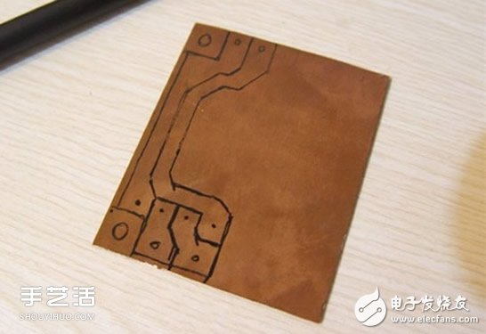
First use the marker to design the component position and wiring on the copper plate according to the components to be arranged. I used to use the method of carving the yin, that is, the insulation tape between the line and the line is left, leaving a large area of ​​the wire, which is more labor-saving. (I haven't tried the corrosion method yet, I feel more troublesome)
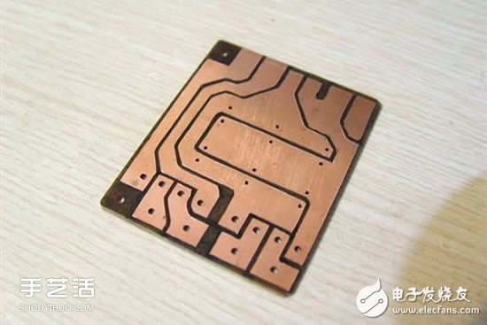
There are a few processes left here. Use a utility knife to draw a double line along the drawn line, and pick up the middle one with a knife tip and tear it off. Rubbing with an eraser, the oxide layer is all gone, revealing a sparkling metallic color. (The board is very small, 60 × 70 mm, it is very tired eyes)
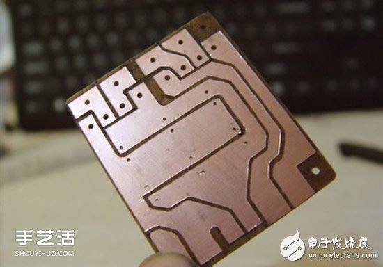
Take it up çž…çž…
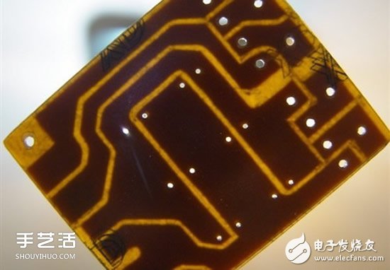
Back under the light, amber
Because TA2024 needs DC single 12V, the maximum can't exceed 13.5V, so you have to transform the transformer, remove the coil a little bit, and remove it to about 10-11V. The load voltage after rectification and filtering is just 12V, and the removed copper wire should not be wasted. When you just wrap it back and use it as a power source for the indicator light, you don't "steal" the power of the amplifier (the photo is after the transformation).
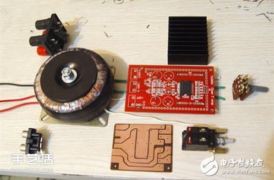
Main accessories: speaker output terminal, transformer, audio input terminal, heat sink, TA2024 board, rectifier board, power switch and volume potentiometer.
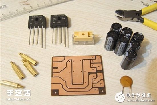
Rectifier components: two 808G bridge stacks (small point for this small power amplifier), fuses, seven 1000μF50V electrolysis (one of which is the indicator light filter, no good filtering, I feel that the whole machine has not burned That part), 0.1pF ceramic capacitor and the previously engraved board. (The copper column next to it is for the "main board")
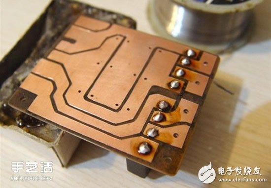
Solder the components one by one
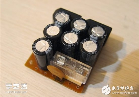
The way the rectifying plate is completed. (All said that the power filter value of TA2024 is 6000-10000. I think the low frequency of 6000 is already enough. The use of multiple small-capacity electrolysis is mainly space limitation, and also increases the charge and discharge speed to get better. Transient corresponding)
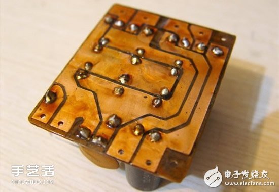
Since there is no special anti-rust paint, I applied a layer of rosin to it to prevent the copper from rusting.
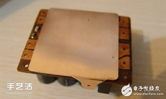
A copper plate is used to simply add a shielding layer to the rectifying plate, and the inner surface is covered with an insulating film and then adhered to the board.
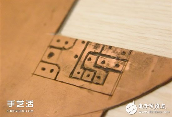
Add a small board to the volume potentiometer so that the connection is convenient. (The isolation layer inside the audio shielding line is Teflon, which is relatively hard, and the direct soldering is easy to break)
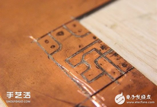
This board is smaller, so it is cut after cutting. (There is a knife on the side that has gone wrong, but fortunately it has not been scratched)
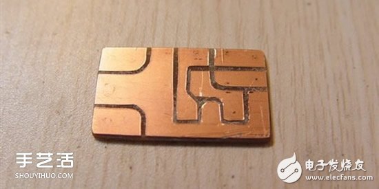
Engraved, wiped
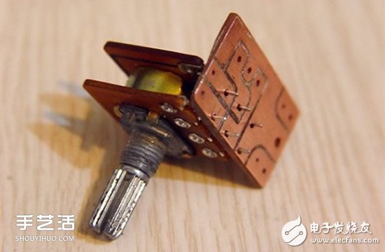
Drill the hole and plug the potentiometer. (The biggest disadvantage of this potentiometer is that it is easy to get into the dust, and now it is closed with a plastic case.)
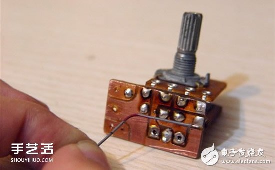
When I designed the line, there was no place to burn it. I had to "fly the line".
Start the processing of the "motherboard", first position the mounting screws according to the width of the board.
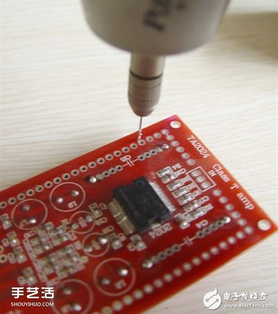
First use a small drill to punch holes in the non-main line of the board.
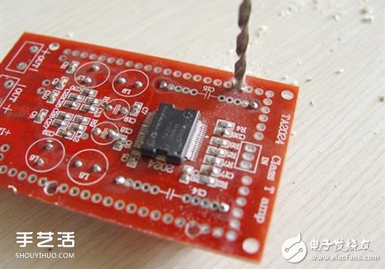
Reaming with Φ3.2 drill bit
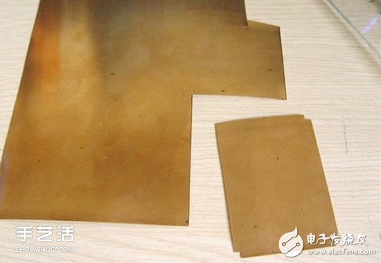
Prepare to use a copper skin to make a shield for the "board"
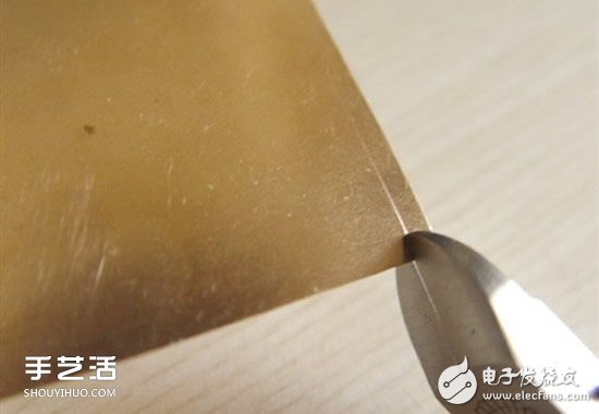
Draw an unfolded picture by the method of origami as a child, and then cut it with a wire cutter
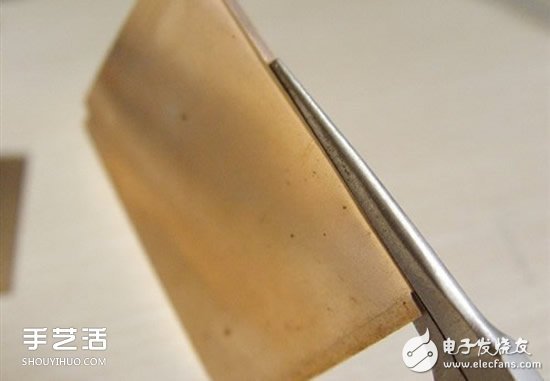
Clamped with a long mouth, toothless forceps, bent and formed
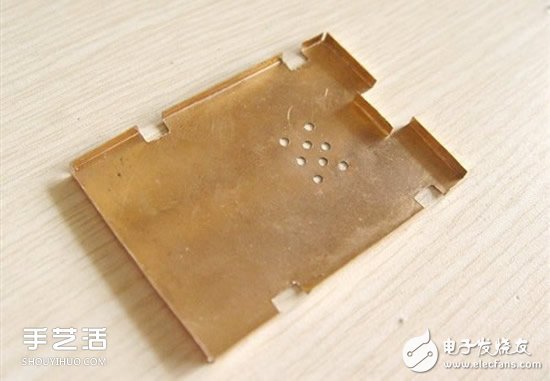
Final cut front shield shell
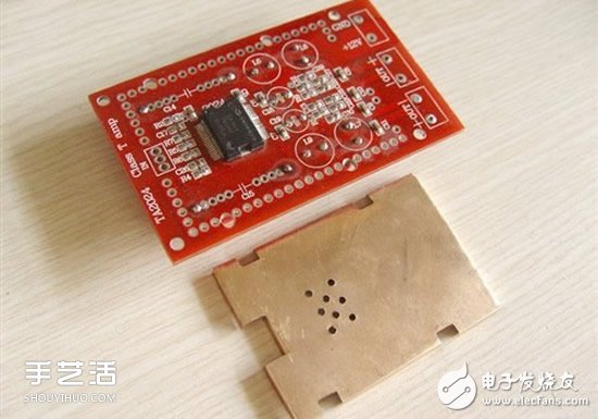
The notch is aligned with the mounting screws and the connection points
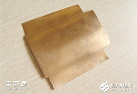
The same method to cut the shield shell on the back
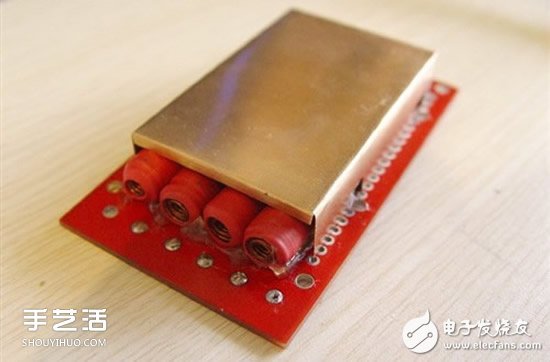
The holes in the outer ring of the board are grounded. It is estimated that it should be designed for the installation of the shield shell, which may be saved in order to save costs.
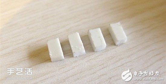
Made four small pieces with ABS plastic
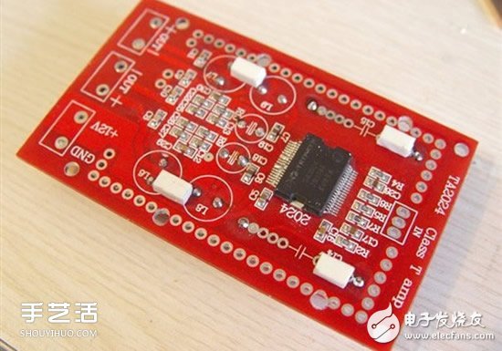
Stick to the front of the "main board" and the height of the IC to prevent the screw from tightening when the heat sink is installed.
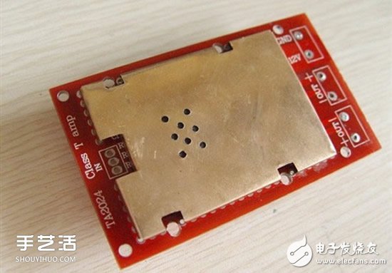
After applying the thermal grease to the IC, solder the shields on both sides to the holes of the outer ring.
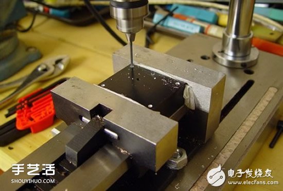
Drilling the heat sink
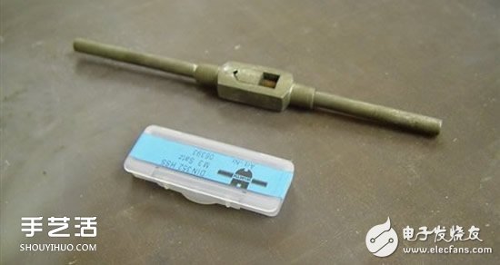
M3 tap and taper shank
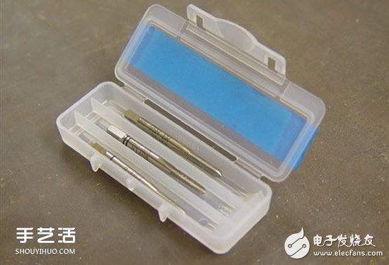
This is a German imported tap, three models for each model, so the screw is very smooth and precise.
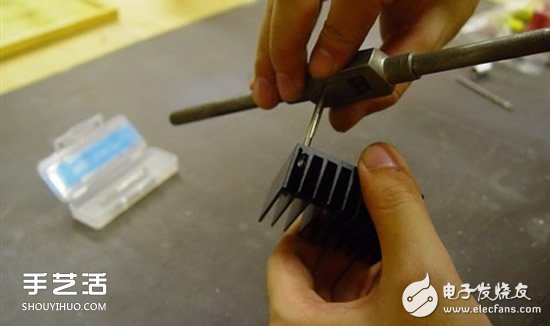
Aluminum is very soft, it doesn't take much to attack
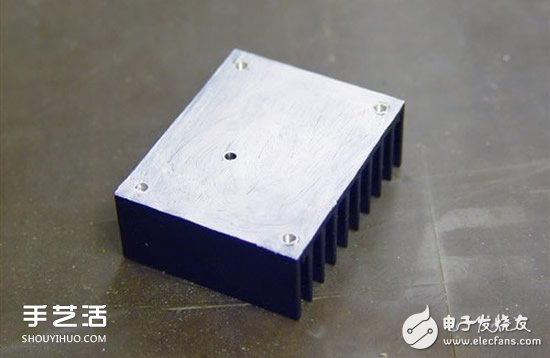
Coated with thermal grease
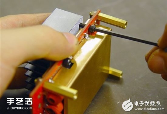
Use a hexagonal M3 screw to heat the heat sink, and put the support column on the way.
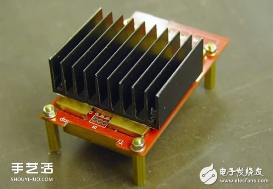
"Motherboard" equipment is completed
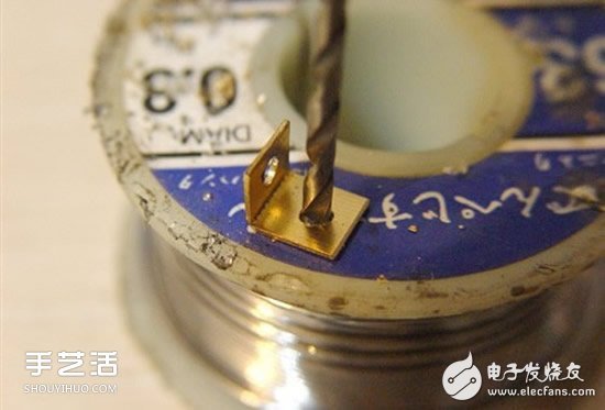
Now use a thick copper plate to make a foot for the rectifier board.
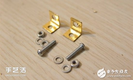
Small screw for M1
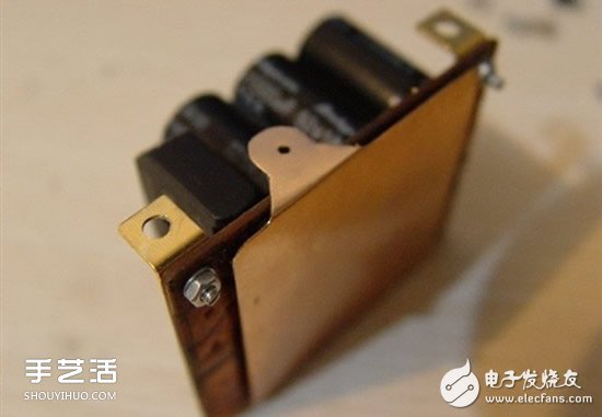
This board is upright, you have to use this foot
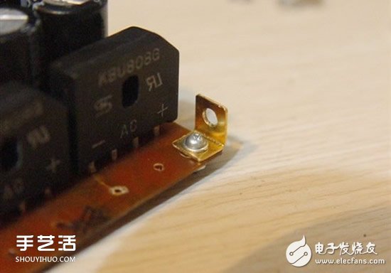
Partial close-up
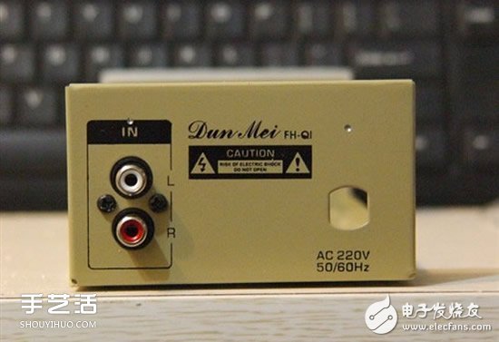
A box for amps bought on a treasure of 60 yuan
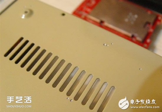
Cooling holes on all sides
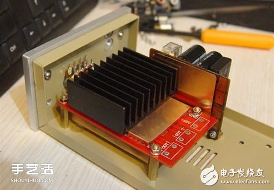
Since the previous boards and components are the approximate size of the purchase, we need to stack all the components at this time to see if the space is suitable.
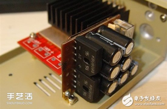
The rectifying plate is mounted like this, just 1 mm from the side
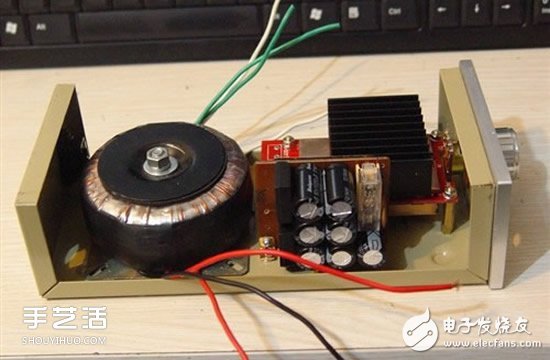
Have a good look
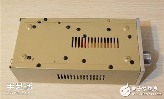
The bottom plate has drilled a lot of holes
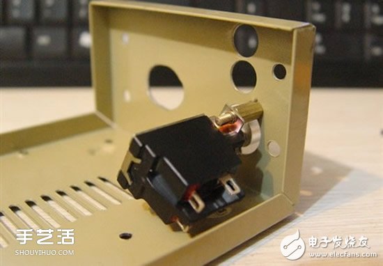
The power switch is better, but it is only a big one.
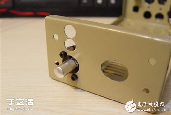
And the original headphone jack position, now changed to the power switch
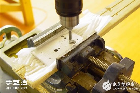
The panel needs to be milled two holes to allow the thickness of the mounting nut of the power switch to be turned on.
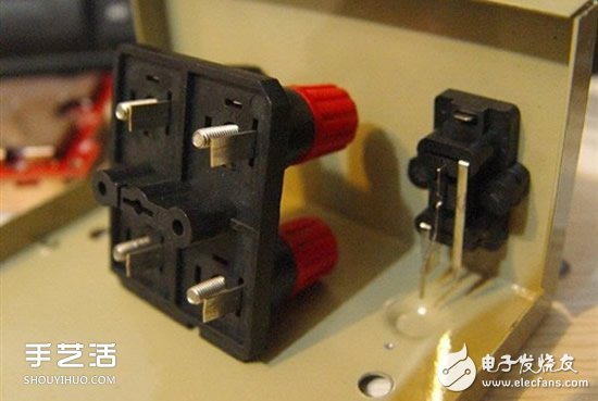
There is no speaker output hole on the back of the amp box, only input
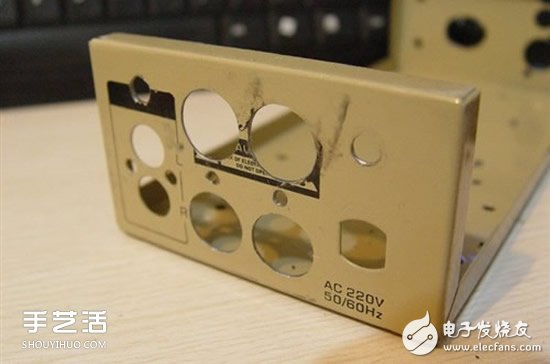
Φ10 large drill hole punching, and then Φ15. (There is no Φ15 drill bit, picking up the hands and peeling ~~)
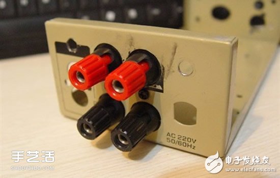
Finally installed. (Well! The hole is a bit big, make it up)
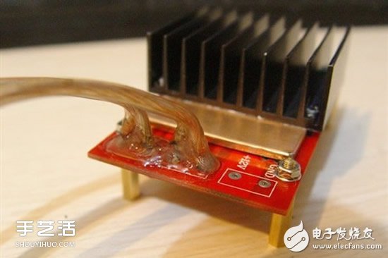
The components are basically complete and the connection is started! First output line
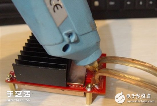
The line is very thick relative to the board, and the joint is fixed by hot melt glue to prevent the copper from falling off.
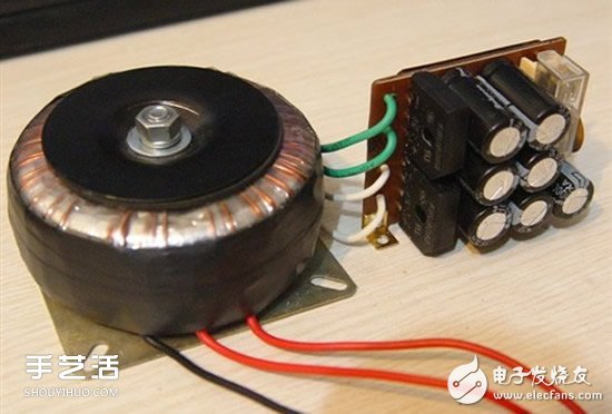
Connect the ring cow and the rectifying plate, calculate the length
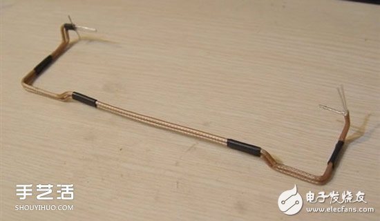
Audio input line. This is more difficult, because the audio line is a coaxial shielded wire, and the toughness is large, so the length is fixed in advance and the shape is convenient for welding.
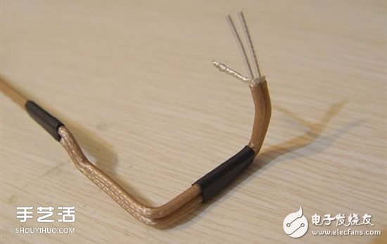
This is the line that the audio line is stripped.
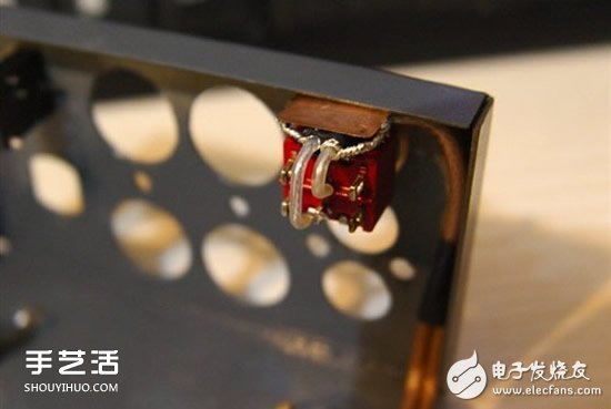
In order to facilitate the switching of the sound source, two sets of inputs, a pair of lotus holes and a headphone hole are made. A selector switch has been added here. (In the middle, I forgot to take a picture of the paint on the outer shell. At this time, the outer shell is already matt dark gray).
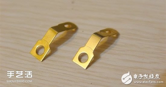
I found two pieces of copper to fix the traces.
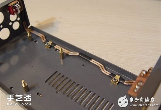
Fixed audio input line, the middle bend is the position where the screw hole of the outer casing is installed.
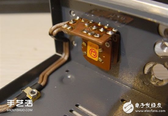
Connection potentiometer
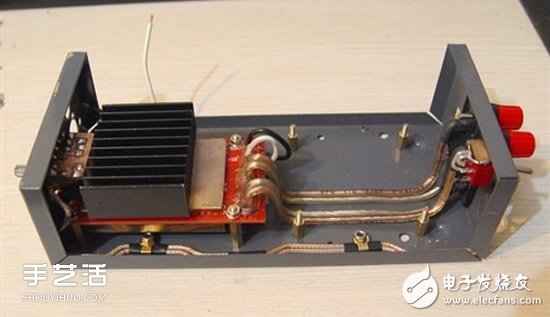
Connect the speaker cable and seal the connector with a heat-shrinkable tube to prevent short
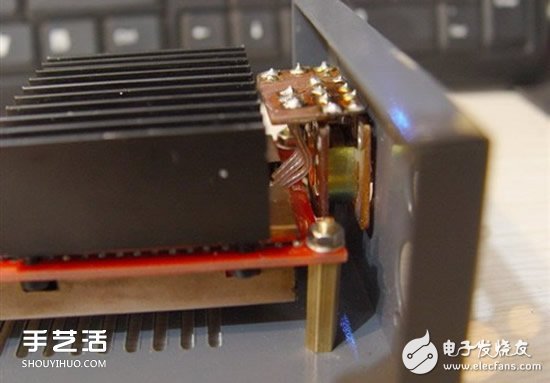
The potentiometer is connected to the "main board" (there is a very close fit here)
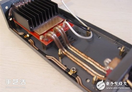
The output line passes under the transformer and the line is very soft
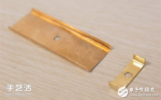
Make a fixed shell for the output line, and have some shielding effect (in fact, the output does not need to be shielded, but the psychological effect does not feel bad).
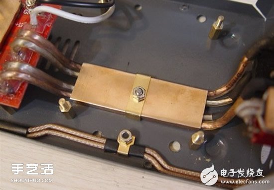
Fixed output line
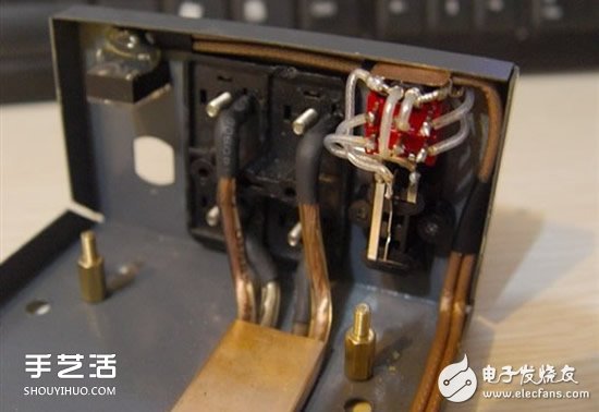
Then look at the two sets of input connections, are shielded lines
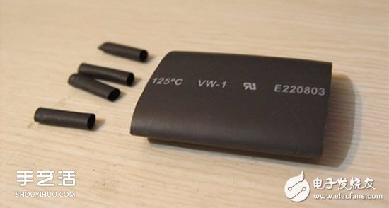
Cut a thick heat-shrinkable tube at one end
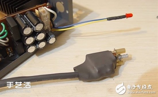
Wrap the connector of the power switch
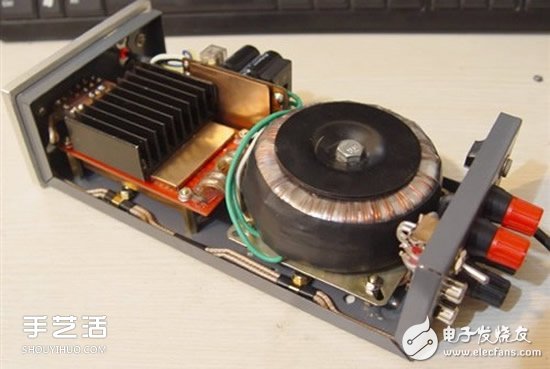
All installed, feels very compact (the transformer is supported by four 10 mm copper posts)
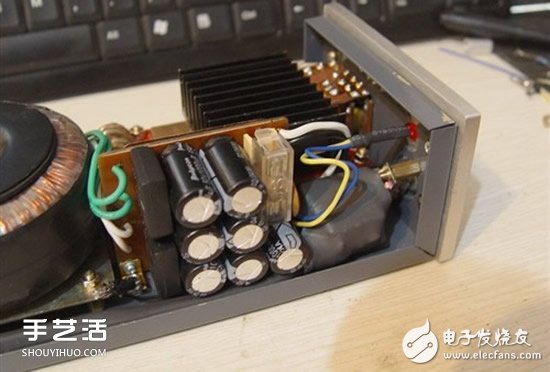
Some details
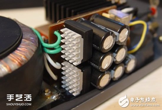
Bored, sticking the memory heatsink on the bridge stack, no practical significance, the light map looks good. Because, 808G is cold in this low-power amplifier.
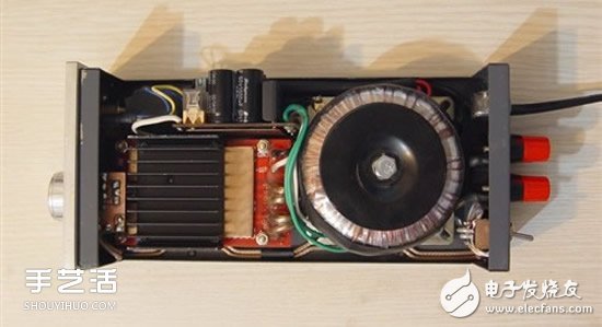
Basically completed, first come to a top view
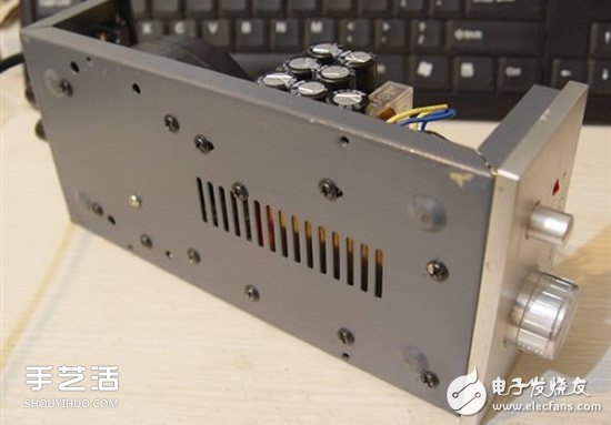
Chassis (last posted four rubber feet, forgot to shoot)
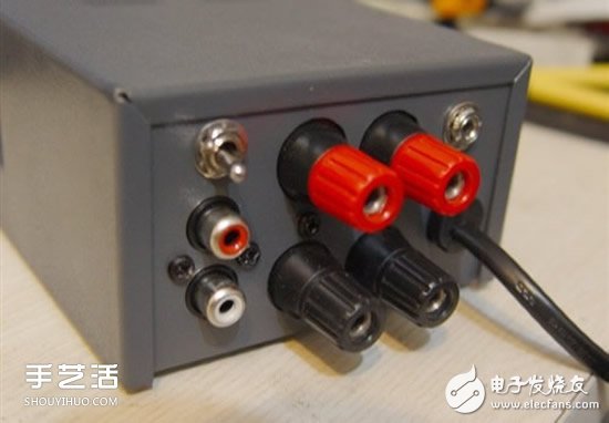
Because there is no screen-printed factory nearby, and taking it to Guangzhou is too small, so the rear terminals are not marked.
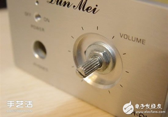
Panel: The above words are originally there, I really want to polish the reprint, but I have no conditions to get it.
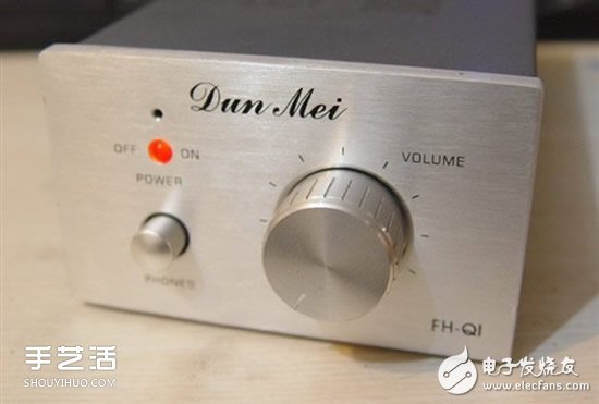
Finished product panel
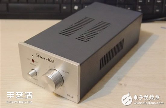
OK! Finished!
The overall feeling is that the TA2024 can also be used to push ordinary multimedia desktop speakers. Since the rated power is only 15W, the unit with a diameter of 6.5 inches or more is very difficult.
Thermal Printer ,Thermal Label Printer,Thermal Receipt Printer,Bluetooth Thermal Printer
ShengXiaoBang(GZ) Material Union Technology Co.Ltd , https://www.sxbgz.com