The exponential growth in cloud service scale has driven significant advances in data center, network and telecom equipment. The number of Internet of Things (IoT) devices connected to the cloud via Internet Protocol (IP) addresses has exceeded the number of people on Earth. These growths have had a huge impact on servers, storage, and network switches that handle ever-increasing data and video, pushing the processing power and bandwidth of infrastructure equipment to the limit. For power supply design engineers, the main challenge is how to efficiently power and dissipate these devices while minimizing power usage.
Engineers must balance board power footprint and heat dissipation while using today's advanced processors, ASICs, and FPGAs.
This paper reviews the evolution of multiphase converter architectures and compares different control mode schemes. It also introduces a new family of multiphase controllers with integrated current control. This advancement in control technology enables power solutions to provide cycle-by-cycle current balancing and faster transient response while tracking each phase current with zero latency.
Multiphase technology evolved to power IoTAs the functionality of the terminal system continues to increase, so does the demand for processing power. Processing power is concentrated in the data center, where high-end CPUs, digital ASICs, and network processors run servers, storage, and networking equipment. They are distributed over the network through telecommunications equipment for transaction processing in PoS machines, desktop computers or embedded computing systems using CPUs or FPGAs.
What these devices have in common is that their digital processing requirements have similar power profiles. As processor sizes decrease and the number of transistors increases, processors now require higher output currents ranging from 100A to 400A or higher, depending on their complexity. This trend has been going on for many years and the industry has been able to adapt by integrating lower power states into digital loads. This allows the digital load to consume lower currents when not in use and to reach peak power when needed. However, while this contributes to overall system power distribution, it presents another challenge for power engineers. On the one hand, it is still necessary to provide more than 200A of full load current and thermal management. On the other hand, the power supply must react to a large load step exceeding 100A in less than one microsecond while keeping the output within a narrow voltage regulation window. .
In end systems, a common solution has been to use a multiphase DC/DC buck converter to provide the required power conversion, typically from a 12V input to an approximately 1V output. To provide large load currents, designing a multiphase solution that distributes the load across multiple smaller stages (called phases) is easier than providing it through a single stage. From the point of view of (I^2)*R, wanting to handle excessive current in one phase poses challenges for designing magnetic components and FETs as well as thermal management. For high current requirements, multiphase solutions offer higher efficiency, smaller size and lower cost than single stage solutions. This method is similar to the technical direction taken by the terminal load, that is, the multi-core CPU divides the workload. Figure 1 shows a multiphase solution that uses 150 phases to deliver 150A to the CPU.
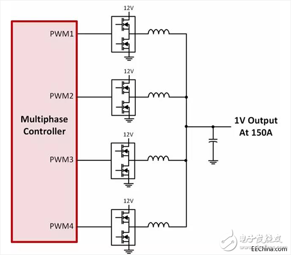
Figure 1. Multiphase solution with four phases
Suitable control schemeMultiphase solutions provide the best power architecture, but the implementation needs to be carefully evaluated to match the latest generation of processors. The trend in end systems is always stronger performance, smaller size and better power management. This trend is reflected in power supply design by minimizing the size by increasing the switching frequency and managing lower input voltages with higher currents under full load and transient conditions. These trends have led to problems in power supply regulation, requiring a corresponding improvement in the control loop. The main challenge in the field of multiphase controllers is to manage the current of each phase, which requires consideration of the following points:
• Each phase current must share the load evenly. If there are N phases, the current of each phase should always be Iphase = Iout / N.
• The phase current must be balanced during steady state and transient conditions.
It's important to keep these conditions, otherwise you may have to constantly design the power supply. For example, phase current imbalance during steady state can cause thermal imbalance. Under transient conditions, if there is only one relative load step to react, the inductor size will be significantly too large, contrary to the original intention of the multiphase design.
In order to satisfy the above two conditions, it is important that the control loop always fully understand the phase current and the output voltage without delay or sampling delay.
Integrated current control schemeThere is a new solution to this problem than using a workaround in voltage control to avoid current sensing problems. Using advanced digital control technology, Intersil has achieved breakthroughs in this area. By placing the entire control, monitoring, and compensation in the digital domain, advanced control methodology can be applied, resulting in an integrated current control loop that provides cycle-by-cycle phase current equalization and fast transient response.
The new control scheme originated from the recognition of the following problem: although the high-side current signal is critical in the loop, direct measurement is not possible due to the short turn-on time and high noise environment. The Intersil controller uses a manually generated integrated current signal that is noise-free, accurate, and has no delay. The basic principle is that all parameters involved in determining the phase current can be measured directly in each cycle, allowing the controller to obtain current values, as shown by the current waveform in Figure 2.
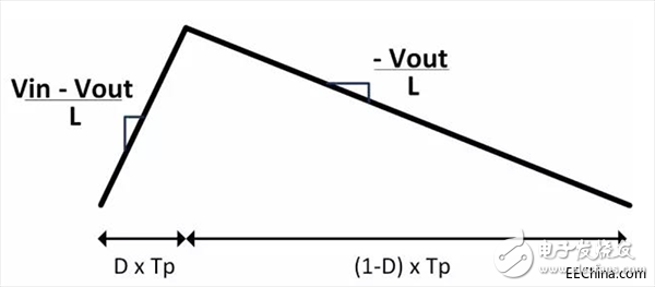
Figure 2. Inductor current waveform
The slope of the current waveform is related to the input/output voltage and inductance. By continuously measuring the voltage and calculating the inductance, a comprehensive current waveform can be generated. Calibration by actual measurements during current down compensation helps the controller eliminate errors due to current offset or slope. This helps the controller to compensate for any changes in the system due to aging, heat generation or inductive saturation. In addition to the internal noise-free current waveform, the controller can also control the loop delay. Since the inductor current ramp is clocked by pulse width modulation (PWM) and the PWM signal is sent from the controller, the digital loop can control all propagation delays through the Intersil Smart Power Stage, eliminating internal current waveform delays.
This feature is only one of the benefits of using the entire loop control in the digital domain with current and voltage information. The block diagram of Figure 3 shows that digital signal processing can be applied in many areas to improve overall response. The implementation of voltage loop compensation uses traditional PID coefficients that can be adjusted in real time through the Intersil PowerNavigatorTM GUI. Transient performance can be further improved by using AC current feedback with a very tight voltage window. By implementing an adjustable filter and threshold, dynamic load changes can be injected directly into the loop, providing a faster response proportional to the load step.
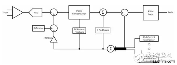
Figure 3. Block diagram of the control loop
Advantages of integrated current controlThe advantage of integrated current control is the ability to design multiphase power supplies with cycle-by-cycle current balancing and fast transient response. The current for each phase is accurately known, allowing the device to remain stable under continuous load transient conditions, with all phases sharing the current evenly. Combined with zero delay in the current feedback path, integrated current control allows the device to respond faster to load conditions, minimizing output capacitance. Even in the case of high current CPUs, an "all ceramic" output capacitor solution can be used. Using zero-delay, full-bandwidth, digital current waveforms, the control loop accurately positions the output voltage according to the load line, mimicking the response of the load distribution curve. This avoids the traditional analog RC attenuation that occurs when the output voltage settles to the new target voltage. Figure 4 shows that the device can still meet any load transient requirements without the need for a load line while stabilizing the device voltage.
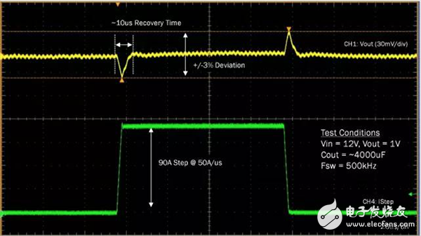
Figure 4. Transient response of the 90A load step
As shown, the integrated current control loop helps the multiphase controller power modern high current loads such as CPUs, FPGAs, and ASICs. Accurate control and positioning of the phase current helps the controller meet any transient conditions with a minimum output capacitance without over-sized inductors.
in conclusionThe multiphase control architecture has entered the digital age, which is very helpful in solving the challenge of powering modern high current loads. This advantage has been reflected in the transient response and phase balance provided by the revolutionary integrated current control scheme. It also brings advantages to many other aspects of power supply design, but has not yet been discussed. One aspect that cannot be ignored is the ability to adjust, control, and monitor settings through software. At a high level, this provides a simpler loop design and tuning scheme because we can use a software interface such as the PowerNavigator GUI to build a complete design in minutes. But when you need to debug the system, the impact on the board is obvious. Instantly understanding the state and conditions of the power supply, as well as compensating for noise conditions through adjustable filters and real-time software control, helps design engineers overcome any challenges without having to redesign the board. These intangible advantages will enable more and more power supplies to adopt digital control solutions.
About the author
Chance Dunlap is the Director of Infrastructure Power at Intersil, a subsidiary of Renesas Electronics. He has 17 years of experience in the power electronics industry, working in applications, business development and marketing, ranging from digital power supplies to isolated power controllers. He holds six patents, has published several technical papers, and has lectured at many symposia and conferences. Chance holds a BSEE from Purdue University and an MBA from the University of Arizona.
The Multiple Power Selection Column Loudspeaker Series which produce good clear sound and acoustical clarity for background music and paging,are suitable for indoor and outdoor applications such as stations, gardens, swimming pools,stadiums, and tennis courts, etc.
Even in extreme weather conditions, the all metal extruded aluminum alloy enclosure with cast aluminium top and bottom plates are fully dust and weatherproof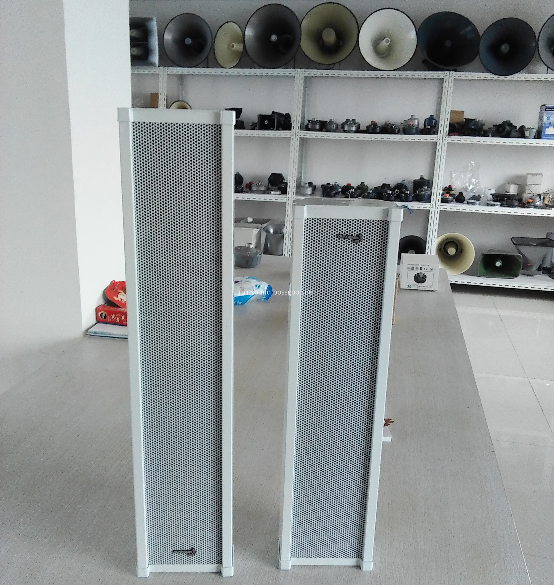
Column Speaker,Column Speakers,Sound Column, Column Loudspeaker, Aluminium Alloy Outdoor Column Speaker
Taixing Minsheng Electronic Co.,Ltd. , https://www.ms-speakers.com