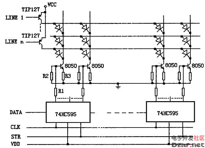
Led display drive circuit (Figure 1)
LED display conventional drive circuit design LED display drive circuit design, in conjunction with the control system used, usually divided into dynamic scan drive and static latch drive two categories. The following is an example of the design of the dynamic scanning type driving circuit for analysis:
The dynamic scanning type driving mode means that four rows, eight rows, 16 rows and the like, n rows of LEDs share a set of column driving registers, and the time-sharing operation of the row driving tubes makes the lighting time of each row of L ED account for The total time of 1ö n, as long as the refresh rate per line is greater than 50 Hz, using the visual persistence effect of the human eye, one can see a complete text or picture [ 2 ]
.
Conventional driver circuits are typically designed with a serial integrated circuit chip such as the 74HC595 or
The MC14094 is latched as a column data, driven by a small power N PN transistor such as 8050, and a Darlington triode such as TIP127 is used as a row scan tube. The circuit is shown in Figure 1.
If a monochrome dot matrix, 16 rows × 64 columns is used as a basic unit, 8 pieces of 74HC595, 64 8050 and 16 are required.
A row of scanning tubes, which works as follows:
Eight 74HC595 are cascaded to share one serial clock CL K and data latch signal STR. When the data to be displayed in the first line is shifted into the 74HC595 after 8×8=64 CL K clocks, a data latch signal STR is generated to latch the data in the latter latch of the 74HC595. The 8050 corresponding to each output bit will be saturated or turned off; at the same time, the line scan control circuit generates a signal to make the first row of scan tubes turn on, which is equivalent to the first line L ED
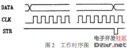
The positive end is connected to the high level. Obviously, the first line of the L ED tube is turned on and off depending on the signal latched in the 74HC595. While the first line of the L ED tube is lit, the second line in the 74HC595 is moved to the second line. The data is then latched, and at the same time the row scan control circuit turns off the first row of scan tubes and turns on the second row, causing the second row of L ED tubes to illuminate... and so on, when the sixteenth row is scanned After returning to the first line, as long as the scanning speed is high enough, a complete text or image can be formed. The working timing is shown in Figure 2.
Defects of the conventional drive circuit Although the design structure of the conventional drive circuit is relatively simple, there are two drawbacks:
(1) When a row driving tube is valid, the lighting current of all L ED LEDs corresponding to the row will flow through the row to drive the scanning tube, and the number of LEDs illuminating the L ED in one row will be displayed as shown. The text or graphics are constantly changing, so the current flowing through the scanning tube has a large change, which will change the tube pressure drop;
(2) illuminating the L ED tube and causing the current change will also affect the fluctuation of the power supply voltage value, which will affect the voltage across the first row of L ED tube, so that it will continue to display text or graphics with different Fluctuation affects the uniformity of the brightness of the entire display.
Therefore, the author designed a column constant current driving circuit, which can eliminate the influence of the fluctuation of the power supply voltage and the change of the voltage of the scanning tube on the brightness of the L ED display. Figure 3 shows the relationship between the relative brightness of a light-emitting diode and the current flowing through it [3].
It can be seen from the curve: In a certain forward current working range, the luminance of the light is approximately proportional to the current flowing therein, and belongs to the current-driven device. Therefore, as long as the current flowing through each LED tube is guaranteed to be constant, the brightness can be ensured.
As can be seen from the working principle of the conventional driving circuit, since the row and column driving tubes all work in a saturated state,
The magnitude of the current cannot be controlled, so the fluctuation of the applied power supply voltage, the change of the voltage drop of the line scan driving tube, etc., directly affects the current flowing in the LED light-emitting tube, that is, changes its display brightness. If the column drive tube is changed from the saturated state to the linear amplification state and becomes a constant current type drive, the uneven brightness of the display screen caused by the above factors can be eliminated.
The column constant current type driving circuit is shown in Fig. 4.
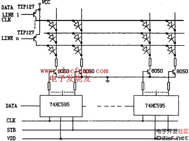
When the power supply voltage VDD is stable, the high-level output voltage V of the 74HC595 is also stable, such as the power supply voltage VDD is 6
V, V = 5. 9V [ 4 ]
. Therefore, when the output of a certain bit of the 74HC595 is high, the L ED of its corresponding column will be illuminated.
And the current flowing through it is approximately: 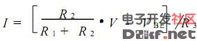
As long as the values ​​of R 1 , R 2 and R 3 are reasonably selected, the current flowing through the L ED is stabilized and can be made
The L ED LED operates at the optimum state of the forward current and the corresponding luminance.
By using this column constant current driving mode, it is possible to change the tube voltage drop of the row driving tube, and the power supply voltage VCC can be changed, regardless of the number of LEDs in the row. The current flowing through the L ED LED is constant, thus ensuring the uniformity of brightness of the L ED display.
5 Conclusion The L ED display constant current drive circuit overcomes the defects of the conventional drive circuit with only minor modifications compared with the original conventional drive circuit, ensuring perfect performance, and the author passes multiple display screens. The actual use has achieved an ideal display effect.
Anti-microbial Hydrogel Screen Protector
Bacteria are everywhere in our daily lives. Mobile phones have become an indispensable item for us. Of course, bacteria will inevitably grow on the phone screen. The antimicrobial coating used in our Anti Microbial Screen Protector can reduce 99% of the bacterial growth on the screen, giving you more peace of mind.
Self-healing function
The Screen Protector can automatically repair tiny scratches and bubbles within 24 hours.
Clear and vivid
A transparent protective layer that provides the same visual experience as the device itself.
Sensitive touch
The 0.14mm Ultra-Thin Protective Film can maintain the sensitivity of the touch screen to accurately respond to your touch. Like swiping on the device screen.
Oleophobic and waterproof
Anti-fingerprint and oil-proof design can help keep the screen clean and clear.
If you want to know more about Anti Microbial Screen Protector products, please click Product Details to view the parameters, models, pictures, prices and other information about Anti Microbial Screen Protector products.
Whether you are a group or an individual, we will try our best to provide you with accurate and comprehensive information about Anti Microbial Screen Protector!
Antimicrobial Screen Protector, Anti-microbial Screen Protector, Anti-bacterial Screen Protector, Antibacterial Screen Protector,Anti-microbial Hydrogel Screen Protector
Shenzhen Jianjiantong Technology Co., Ltd. , https://www.jonsun-sz.com