A microstrip antenna is an antenna formed by attaching a conductor patch to a dielectric substrate with a conductor ground plate. The patch is fed by a microstrip line or a coaxial probe, and an electromagnetic field is excited between the patch and the ground plate. , radiating outward through the patch and the slit. The microstrip antenna is widely used in various fields of measurement and communication because of its small size, low profile, light weight, easy feeding, and easy conformal mounting with the carrier. However, since the microstrip antenna is a resonant antenna, the high Q characteristic determines that its input impedance is sensitive to frequency variations, resulting in a narrow band of the patch antenna (the relative bandwidth of the general band is only 2% to 5%). ).
For the microstrip antenna operating in the Beidou frequency band, due to the narrow bandwidth, there is a high requirement for the accuracy of the working frequency. Small changes in the external environment may cause the frequency to drift, resulting in the antenna not working properly. In order to solve this problem, the frequency band around the frequency band of the microstrip antenna can be widened, so that even if frequency shift occurs, the working frequency of the antenna can remain within the working bandwidth of the antenna.
There are many design methods for widening the frequency band of microstrip antennas: increasing the thickness of the dielectric substrate, but this will introduce surface wave loss; reduce the relative dielectric constant of the medium, but increase the size of the substrate; Parasitic elements will also increase the area of ​​the substrate; increase the impedance matching network; slot-coupled feed; use a multi-layer structure.
In this paper, the structure of adding air layer between the two-layer patch is adopted, and the mutual coupling between the two patches is used to generate two similar resonance frequency points, thereby increasing the frequency bandwidth of the microstrip antenna. The structure, theory and simulation structure of the microstrip antenna are discussed below, and the conclusion is given at the end.
1 Microstrip antenna design1. 1 structure of double-layer microstrip antenna
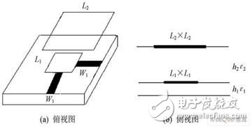
The structure of the microstrip antenna is shown in Figure 1. Different from the traditional microstrip antenna, the coaxial probe is used to feed the patch. In this paper, the orthogonal microstrip line is used to feed the patch, which can avoid the same The use of an axial probe introduces an inductance, which is inconvenient for impedance matching of the antenna, and can also simply realize the circular polarization function of the antenna. The two orthogonal microstrip lines have the same width and are all W1. In addition, as can be seen from the figure, an air layer is added between the two patches to reduce the dielectric constant, thereby increasing the bandwidth.

Figure 1 Top and side views of a two-layer microstrip antenna.
1. 2 theoretical analysis of double-layer microstrip antenna
The specific derivation steps are as follows. Assume that the resonant frequency of the lower patch is f 01 and the side length is Le1. The resonant frequency of the upper patch is f 02 and the side length is Le2.

Where: c is the speed of light in free space.

Where: ε1 and ε2 represent the relative dielectric constant of the underlying dielectric substrate and the relative dielectric constant of the upper dielectric substrate, respectively; h1 represents the thickness of the underlying dielectric substrate; h2 represents the thickness of the air layer.

Where: L ei and L i represent the actual side length of the patch and the elongation of the patch, respectively; εei is the effective dielectric constant.
1. 3 double-layer microstrip antenna size parameters
The substrate used in this paper is the dielectric substrate of T ACNIC, 1 = 2. 65, h = 0. 5 mm. Among them, the upper patch L 2 = 95 mm, the lower patch L 1 = 70 mm; the thickness of the underlying dielectric substrate is h1 = 1 mm, the thickness of the middle air layer is h2 = 13 mm, and the dielectric constant is 2 = 1 0 (It is also possible to use a foam material with a dielectric constant close to 1 instead of the air layer. The air layer is chosen to achieve the purpose of reducing the effective dielectric constant). After several simulation experiments, it is found that the microstrip antenna can obtain better impedance matching when W1 = 6. 4 mm.
1. 4 Simulation results and analysis of double-layer microstrip antenna
Based on the above parameters, the microstrip antenna designed in this paper was simulated by A nsoft HFSS. The simulation results are as follows:
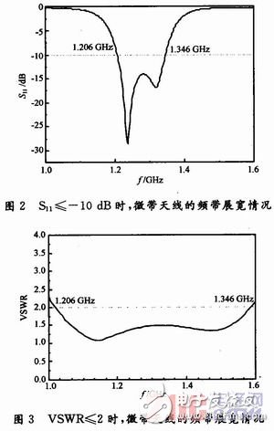
Figure 2 shows the band broadening of the microstrip antenna at S11 "= - 10 dB, and Figure 3 shows the band broadening of the microstrip antenna with VSWR "= 2.
STyle=“FILTER: ; WIDTH: 450px; HEIGHT: 344px†height=344 alt=“S11 <<=10 dB, the band broadening of the microstrip antenna†hspace=0 src=“http://files.chinaaet. Com/images/20110105/64bd0cef-994b-4b9c-b63c-5d1c74bd9df0.jpg" width=450 border=0"

As can be seen from Fig. 2 and Fig. 3, the operating band of the microstrip antenna is between 1.206 and 1.346 GHz, the center frequency is 1.276 GHz, and the frequency is very close to the Beidou frequency of 1.268 GHz. The width reaches BW=140 MHz, and the relative width is 11.04%, which far exceeds the working bandwidth range of the ordinary microstrip rectangular patch antenna (the average bandwidth of the common microstrip antenna is about 2% to 5%). Appropriate adjustment of the thickness of the air layer can also control changes in the resonance point. In addition, as can be seen from Fig. 2 and Fig. 3, there are two resonance frequency points in the working frequency band, which are caused by the resonance of the upper and lower patches, and it can be seen that the two-layer patch can be generated. Two resonance points, which can effectively achieve the purpose of widening the microstrip antenna band.
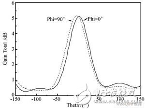
It can be seen from Fig. 4 that the gain of the double-layer microstrip antenna reaches 5. 2 dB, which is slightly increased compared with the gain of the conventional microstrip antenna. It can be seen that the dual-strip microstrip antenna also has a certain gain in gain. Contribution. To greatly increase the gain of the microstrip antenna, you can attach a layer of ε r " 1 dielectric substrate to the top layer.
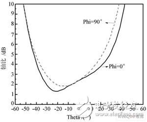
It can be seen from Fig. 5 that the partial axial ratio of the microstrip antenna is less than 3 dB, thereby achieving circular polarization of the antenna, but the maximum radiation direction of the microstrip antenna deviates from the axial direction, and the axial ratio of the antenna is deteriorated. The microstrip antenna can basically meet the requirements of circular polarization.

Figure 4 Gain of the microstrip antenna.

Figure 5 Simulation of the axial ratio of the microstrip antenna.
2 ConclusionAiming at the narrow band of the microstrip patch antenna, this paper proposes a dual patch microstrip antenna structure that uses orthogonal microstrip lines for feeding.
In VSWR "= 2, the frequency range is between 1. 206 and 1. 346 GHz, the bandwidth reaches 140 MHz, and the relative bandwidth reaches 11.04%. In the working frequency band, the gain of the antenna is slightly increased, and the axial ratio is acceptable, so the antenna structure is a relatively economical and practical microstrip antenna structure.
Intel Nuc Gaming,Mini Itx Pc,Small Gaming Pc,Micro Gaming Pc
Guangdong Elieken Electronic Technology Co.,Ltd. , https://www.elieken.com