Satellite communication has the characteristics of wide coverage, available frequency bandwidth, fast network construction and low cost, which has been widely used in the field of communication. With the development of satellite communication, in order to meet the requirements of effective omnidirectional radiated power (EIRP) in a certain ground service area, the communication antenna must be forced to adopt a multi-feed shaping or reflecting surface shaping antenna, which greatly promotes multi-feed. Development of source shaped or reflective surface shaped antennas. This can reduce the interference generated by the ground station outside the coverage area to the satellite system, improve the spectrum utilization and channel capacity of the system, and improve the effective isotropic radiated power (EIRP) and the receiving system quality factor G/T value. Simplify and reduce the cost of satellite ground station equipment.
When the coverage area is a map of China's political district, considering that China's western region is vast, sparsely populated, and has small rainfall, while the eastern region is densely populated, economically developed, and has large rainfall, rain attenuation is an important consideration for satellite communications. problem. Therefore, it is necessary to take into account both the appropriate power coverage in the country and the emphasis on the North China region in the eastern region, so that it has a higher power allocation; while the western region is slightly reduced to make full use of satellite resources. In this way, the communication beam generated after shaping the antenna can cover both the whole country and the east. In order to prevent signal interference, the main and cross-polarization gains of the antennas in the direction of the neighboring countries should be sufficiently small. In short, for a constant area, as long as some major factors are taken into account, a rough expected distribution can be obtained.
1 Shaped antenna overviewShaped antennas are classified into two categories according to whether the reflection surface is variable: (1) Single shaped antenna and reconstructed shaped antenna. (1) Single-shaped antenna refers to an antenna that has a single use and is not changed after assembly and transmission. The coverage area of ​​the antenna and the spatial position of the antenna are no longer changed, and the target area gain distribution covered by the antenna is determined to be constant. The design of such antennas is usually to design the reflective surface according to the expected coverage area gain distribution analysis, and the reflective surface does not change once it is determined. (2) There are two cases of variable shaped antennas: one is to adjust the working system according to the change of the position of the antenna orbit, so as to obtain the corresponding shaped beam; the second is to adjust the system to produce corresponding shapes for different shapes of the region. Beam coverage [1].
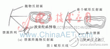
Shaped antennas are divided into two categories according to the number of feeds used: multi-feed antennas and single-feed antennas. In conventional satellite communication, an array feeding parabolic antenna (Fig. 1(a)) is usually used, and the feeding array is placed on a reflecting surface or a focal plane of a microwave lens, and is composed of feeding antennas arranged in a certain manner. The feed array is located on the focal plane, and each feed has a lateral offset with respect to the focus except for the feed at the center, and the offset direction and the offset amount are different, so that the beams generated by the feeds are different. After the reflection of the reflecting surface or the focusing of the lens, a set of sub-beams which are independent of each other, have approximately equal beamwidths, and are evenly distributed are formed in the far-field region. The focus of this antenna's shape design is to optimize the parameters such as the excitation coefficient and geometric arrangement of the feed. One of the important components is the Beamforming Network (BFN), which is used to adjust the excitation of the feed. However, they have inherent disadvantages: a large amount of overhead of the antenna system will be spent designing and adjusting the beamforming network, and complex beamforming networks will cause RF loss and reduce the overall gain of the antenna system. These defects are more severe as the frequency increases, so multi-feed shaping techniques are generally used below the Ka-band (4 GHz to 7 GHz) [2-6].

It is a more feasible solution to shape a single reflecting surface (as shown in Figure 1(b)). In the case of beamforming a fixed area, a beam forming network can be used instead of a reflective surface forming design, and a single-feed forming reflecting antenna is used. The shaped reflecting antenna has simple machining and is not complicated in structure. And because there is no beamforming network, the loss is small and the gain is higher [6-10].
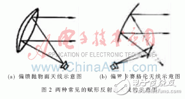
According to the reflector type of the antenna, it can be divided into a single shaped reflecting surface antenna and a multi-shaped reflecting surface (usually two reflecting surfaces) antennas. In the design of the shaped antenna, the single-reflection antenna generally uses a bias-feeding reflector antenna. Figure 2(a) shows an offset-feed parabolic antenna, which is cut by a conical surface with a certain deflection angle to cut the standard paraboloid. Got it. Compared with other antenna forms, it has the characteristics of simple structure and low centroid, and it also solves the problem of occlusion of the feed. Based on this, the antenna is widely used in satellite communications. In the design of shaped reflector antennas, the common multi-reflector antenna is a double-biased reflector antenna. As shown in Fig. 2(b), by shaping the shape of the two reflecting surfaces of the offset Kessler or Gregory antenna (from the viewpoint of design processing, etc., generally only the sub-reflecting surface is shaped) To achieve the purpose of the shape design.

From the perspective of the method of forming, it can be divided into direct method and indirect method. As early as 1975, KATAGI T and TAKEICHI Y proposed a design method for forming reflective surfaces, namely wavefront analysis methods, which were then based on geometric optics (GO) and physical optics (North American and European researchers). PO), geometrical diffraction theory (GTD) and physical diffraction theory (PTD), etc., propose a direct and indirect integrated method for forming reflective surfaces. The optimization method of the direct method [11-12] is the shape of the reflection surface itself. The optimization object of the direct method using various functions expansion method is the shape of the reflection surface itself, and the reflection surface is expressed by various function expansions, and the coefficient of the optimization function is passed. Perform reflection surface synthesis. In general, it is very difficult to find such a basis function according to requirements. Most of these methods are formal representations of series. The indirect method is optimized for some characteristic parameters of the shaped reflector antenna, such as wavefront and aperture field distribution. By optimizing these parameters to meet the shape requirements, some nodes of the reflection surface are determined, so as to fit and determine the reflection. The shape of the face. Whether it is a direct method or an indirect method, it is just an optimization process. In this way, finding the best optimization method is the key problem. The optimization result of testing a method can be obtained from the later error analysis. Whether the test method is feasible in practice or not must be verified by strict physical methods.
2.1 wavefront method
Cross-arm Insulator,composite cross arm insulator,cross arm insulator,cross arm insulator pin
TAIZHOU HUADONG INSULATED MATERIAL CO.,LTD , https://www.thim-insulator.com