Secondary circuit Definition: All low-voltage circuits such as measurement circuit, relay protection circuit, switch control and signal circuit, operating power circuit, circuit breaker and electrical lockout circuit of isolation switch. An electrical circuit that is connected to each other by a secondary device to form a monitoring, control, regulation, and protection of the primary device is called a secondary circuit. It is a circuit that is connected in the electrical system by a secondary winding of a transformer, a measurement monitoring instrument, a relay, an automatic device, etc. through a control cable. It is used to control, protect, regulate, measure and monitor the working conditions of various parameters and components in the primary circuit. The circuits used to monitor the electrical connections formed by the meter, the control signal, the relay protection, and the automatic device are referred to as secondary circuits or secondary wires.
Detailed secondary circuit
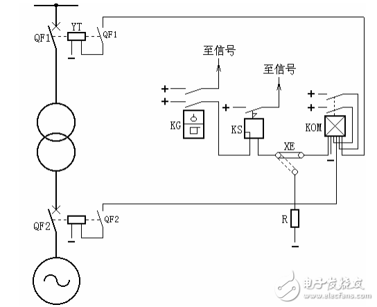
17. According to Figure 19, the composition and operation process of transformer gas protection
Answer: The main component of transformer gas protection is the gas relay, which is installed in the connecting pipe between the fuel tank and the oil pillow. When the transformer has an internal fault, the oil expands and the generated gas flows along the connecting pipe gas relay into the oil sump. If the flow speed reaches a certain value, the baffle of the gas relay is impulsive and tilted to one side, closing the contact of the gas relay, turning on the trip circuit or signaling, as shown.
In the figure: the upper contact of the gas relay KG is connected to the signal for light gas protection; the lower contact is for heavy gas protection, after the signal relay KS and the connecting piece XE start the outlet intermediate relay KOM, after the two pairs of contacts of the KOM are closed, The circuit breakers QF1, QF2 and the trip coil are respectively excited. Jump off the circuit breakers on both sides of the transformer, ie
DC + → KG → KS → XE → KOM → DC -, start KOM.
DC + → KOM → QF1 → YT → DC -, trip circuit breaker QF1.
DC + → KOM → QF2 → YT → DC -, trip circuit breaker QF2.
Further, the connecting piece XE can also be connected to the resistor R, so that the heavy gas protection does not trip and only signals.

Figure 19 wiring diagram of transformer gas protection principle
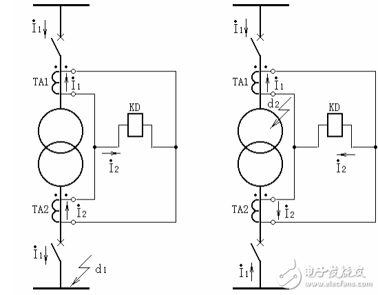
18. Explain the name and operation process of the symbol component according to Figure 20.
Answer: Transformer differential protection is based on the principle of circulating current. It can correctly distinguish the internal and external faults of the transformer and can instantly remove the fault in the protection zone. Figure 20 shows a single-line schematic of the differential protection of a two-winding transformer. Current transformers TA1 and TA2 are respectively installed on both sides of the transformer, and are connected according to the polarity relationship shown in the figure.
When the fault occurs normally or externally (d1 point in Figure a), the current in the differential relay KD is equal to the difference between the secondary currents of the current transformers on both sides. To make the current flowing through the differential relay 0 in this case, Properly select the changes in the current transformers on both sides. Since the secondary rated current is generally 5A, the change of the current transformer is: primary rated current / secondary rated current, UN/5. Ignore the excitation current of the transformer, then flow into the differential relay during normal operation or external fault. The current is 0.
When the inside of the transformer is faulty at point d2 in Figure b, the current flowing into the differential relay is the sum of the short-circuit currents (secondary values) flowing to the short-circuit point on both sides of the transformer.
In fact, due to the influence of the inrush current of the transformer, the wiring mode and the error of the current transformer, the unbalanced current flows in the differential relay. The larger the unbalance current, the larger the operating current of the relay, resulting in the differential protection. The sensitivity is reduced. Therefore, one of the main problems that need to be solved by differential protection is to take various measures to avoid the influence of unbalanced current. Under the condition of ensuring selectivity, it is also necessary to ensure sufficient sensitivity and quickness in internal faults.

(a) during normal operation or external failure (b) internal failure
Figure 20 Schematic diagram of single-wire schematic for differential protection of two-winding transformer
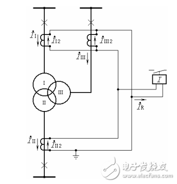
19. According to Figure 21, the composition and working principle of differential protection of three-winding transformer
Answer: The operating principle of the differential protection of the three-winding transformer is the same as that of the differential protection of the two-winding transformer. It is also constructed according to the principle of circulating current. In normal operation and external short circuit, the three-side current vector of the three-winding transformer and (converted to the same voltage level) are zero. It may flow from one side to the other, or it may flow in from both sides and out from the third side. Therefore, if any two side currents are added and compared with the third side current, the differential protection of the three-winding transformer is formed. The principle wiring is shown in Figure 21.
In normal operation and external short circuit, if the unbalanced current is negligible, the current flowing into the relay is zero.
iR=iI2+iII2+iIII2=0
When the internal short circuit occurs, the current flowing into the relay is
iR=iI2+iII2+iIII2=∑iK/na
That is equal to the sum of the short-circuit currents (secondary values) on each side.
It can be seen that during normal and out-of-zone short circuit, the protection will not operate, and in the event of an internal fault, the protection will be sensitive.
In order to protect the reliability and sensitivity of differential protection of three-winding transformers, the following points should be noted:
(1) The ratio of the current transformers on each side should be selected according to the maximum rated capacity of the transformer.
(2) The three-winding transformer in the case of external short circuit has larger unbalance current than the double-winding transformer. It is better to use the BCH-1 differential relay with braking characteristics. If the BCH-1 still does not meet the sensitivity requirements, two Differential protection for subharmonic braking.
(3) In order to solve the unbalanced current caused by the inconsistency between the actual variable and the calculated transformation ratio, to ensure the balance between the coils on each side, for the BCH-1 differential protection, the two sets of balance coils should be connected to the second time. The sides of the current are smaller.

Figure 21 Single-phase schematic diagram of differential protection of three-winding transformer
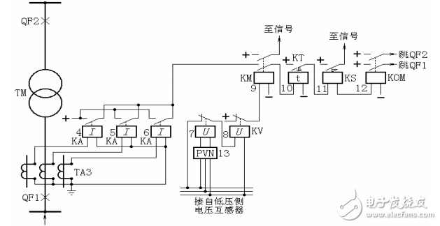
20. According to Figure 22, the composition and operation process of the overcurrent protection of the transformer composite voltage start
Answer: In Figure 22, when an asymmetrical fault occurs in the protection zone, the system has a negative sequence voltage. The negative sequence filter 13 has a voltage output to make the relay 7 normally closed contact open, the undervoltage relay 8 loses pressure, and the normally closed contact closes. The intermediate relay 9 is turned on. If any one of the current relays 4, 5, and 6 operates, the time relay 10 is activated, and after the time limit is reached, the circuit breakers on both sides are tripped. In the case of a symmetrical short circuit, the voltage relay 7 does not start, but the undervoltage relay 8 is turned off due to the voltage drop, and the normally closed contact is turned on, and the protection is started.
The negative sequence voltage setting value can be 6% of the rated voltage; the current setting value can be greater than the rated current of the transformer, but not necessarily greater than the maximum current (for example, when the transformer in parallel operation is disconnected).

Figure 22 Schematic diagram of overcurrent protection for composite voltage startup
We are a professional manufacturer in the cabling solutions supplies in Ningbo, we could offer the Patch Panel in 8-48 ports, cat5e, cat6 cat6a specification; Metal or plastic Cable Management with brush; the Keystone Jack in UTP and STP style; surface wall mount box in blank, cat5e cat6 or other mount box; the RJ45 Modular Plug in 8P8C, cat5e, cat6, cat7 basing on UTP and STP Style; 86 type, UK type, France, type, German type, USA type Face Plate in 1 port to 8 ports; Stripper and Crimping tool and tool kits, cable tester for RJ11 RJ12 RJ45, HDMI,USB connector; cabling solution accessories like as cable tie, Cabinet screw, LSA module frame, indoor and outdoor distribution box, fiber optical distribution box and patch panel.
We have more 6 staffs in QC team, and 4 staffs in technical division to keep the high quality of products and service to our customers.
CAT5E Patch Panel,STP Patch Panel,24 Ports Patch Panel,keystone patch panel
NINGBO UONICORE ELECTRONICS CO., LTD , https://www.uonicore.com