The AD604 is a low noise, high precision, dual channel, variable gain amplifier. It has the advantage that the decibel number of the gain is proportional to the gain control voltage, and is especially suitable for the application of the time gain compensation circuit in the ultrasonic instrument. This paper introduces the characteristics, structure and usage of the AD604, and introduces a typical application circuit based on the ultrasonic attenuation compensation of the chip.
The AD604 is a product of Analog Devices (AD Corporation). Compared with similar products, the AD604 has ultra-low noise, high precision, continuously adjustable gain, and the decibel (dB) of gain is proportional to the gain control voltage. The time gain control (TGC) circuit of medical ultrasonic instruments requires that the gain be exponentially related to the control voltage, that is, the decibel (dB) of the gain is linear with the control voltage. Therefore, in this respect, the AD604 is an ideal ultrasonic TGC amplifier that effectively reduces the dynamic range of the signal sent to the A/D converter.
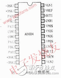
1 pin vv x functionThe AD604 is available in a 24-pin package and is available in DIP, SSOP and SOIC packages. The pinouts are shown in Figure 1. The function description of each pin is as follows:
PAI1/PAI2: preamplifier positive input;
PAO1/PAO2: preamplifier output;
FBK1/FBK2: preamplifier feedback terminal;
COM1/COM2: signal ground; when it is connected to the positive power supply, the preamplifier channel is turned off;
-DSX1/-DSX2: differential attenuator signal input negative terminal;
+DSX1/+DSX2: differential attenuator signal input positive terminal;
VGN1/VGN2: Gain control input and power off terminal. When grounded, the attenuation channel is turned off; otherwise, as the positive voltage increases, the gain will gradually increase;
VREF: Gain control file for both channels. When the voltage is +2.5V, the gain is 20dB/V, and when the voltage is +1.67V, the gain is 30dB/V;
VOCM: The common mode signal control terminal of the output signal. Used to determine the median voltage of the DC signal in this part of the circuit;
OUT1/OUT2: signal output terminal;
VPOS/VNEG: Connect positive/negative power supply;
GND1/GND2: Ground.

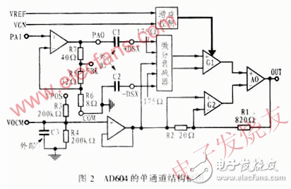
The AD604 is a dual channel variable gain amplifier. Each of its channels consists of a low noise preamplifier and a variable gain amplifier (XAMP). At the same time, XAMP consists of a high precision controlled differential attenuator, a gain control unit, a fixed gain feedback amplifier and a VOCM common mode voltage control unit consisting of discrete components R3, R4. The principle is shown in Figure 2. Each channel of the AD604 provides a variable gain range of 48dB.

2.1 preamplifier
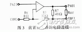
Each channel of the AD604 has a high performance preamplifier that can be controlled from +14dB to +20dB through an external resistor on the feedback loop. The internal circuit of the preamplifier is shown in Figure 3. Among them R5, R6, R7 are the gain control resistors of the preamplifier. The specific gain can be determined by the resistance between FBK1 and PAO1.

2.2 differential trapezoidal network (attenuator)
The preamplified output can be used as a differential input to the exponential amplifier to achieve a decibel linear gain. This attenuator is implemented by a 7th-order R-1.5R ladder network. The attenuation for each order is 6.908 dB, so the final total attenuation is 48.356 dB.
2.3 gain control
The linear gain control of the AD604 is implemented through the VGN side. The user can input the required change voltage to the VGN to obtain a varying gain. The input resistance at the VGN end is 2MΩ.
In order to meet the needs of different users for gain, the AD604 also provides a gain control file. The gain level can be adjusted by adjusting the input voltage of VREF: VREF voltage from 2.5 to 1.25V corresponds to a gain range of 20 to 40 dB/V. For the 20dB/V gain range, the VGN can be adjusted from 0.2 to 1.2V. For the 40dB/V gain range, the VGN can be adjusted from 0.4 to 2.4V. When the current amplification is 14dB, the gain number can be calculated by the following formula:
2.4 fixed gain amplifier
This level of amplification is actually a feedback circuit consisting of an operational amplifier. One of the feedback amplifier outputs can be used as a feedback input; the other is used as an input to the differentiator (see Figure 2).
The total gain of this part of the amplifier is: G total = VOUT / VATTEN = [(R1 + R2) / R2] gm1/gm2. Where VOUT is the output voltage and VATTEN is the readout signal of the attenuator, (R1+R2)/R2=42, gm1/gm2=1.25. Therefore, the total gain is 52.5 (ie 34.4 dB).
3 AD604 application in medical ultrasound equipmentWhen the ultrasonic waves emitted by medical ultrasonic instruments are transmitted through the human body, their energy will be absorbed by human tissues. As the depth of detection increases, the energy of the ultrasonic waves will gradually decay. In order to make the echo amplitudes of different depth tissue interfaces the same, the echo signals at different depths should be attenuated to different degrees to achieve the sound path compensation, that is, the gain of the receiver needs to increase with the increase of the scanning time. Because the amplification signal of the echo signal reflected from the deeper part of the sound interface is larger, and the reflected signal closer to the transducer, that is, the echo signal that arrives earlier in time, the magnification is smaller. In ultrasonic diagnostic instruments, TGC (TIme Gain CompensaTIon) deep time gain compensation circuit is generally used, that is, a certain voltage curve is used to control the gain of the amplifier, so that ultrasonic echoes at different depths can obtain different magnifications, thereby Play a compensation role.
Figure 4 shows a medical ultrasound gain compensation circuit that uses the AD604 to drive the AD9050 (10-bit, 40 MSPS ADC). When the AD7226 D/A converter is interfaced with other microprocessors, the digital value of the read-in amplification should be converted to an analog quantity, and then this analog quantity is input as the gain control signal of the AD604 (ie, connected to its VGN end), thereby Achieve gain control. The AD604 attenuation-compensated signal passes through the filter and the AD9631 (low distortion, low noise, high speed op amp) to become an effective input to the ADC. The output of the op amp and the self-biased input of the ADC are ac-coupled and the analog-to-digital conversion of 40MSPS is performed by the AD9050 A/D converter.

The solution solves the nonlinear compensation problem of the echo signal caused by the sound path in the medical ultrasound soft tissue measurement process. Compared with the traditional discrete component circuit, the scheme has the characteristics of simple circuit, stable and reliable TGC control signal and flexible adjustment, which can accurately compensate the attenuation of ultrasonic waves in the human body, thus providing a new reliable method for high-speed digitization of the control system. .
Wall-Mounted Power Adapter,Wall-Mount Switching Power Adapter,Wall-Mounted Adapter Power Adaptor,Ac Dc Wall-Mount Power Adapter
Guangdong Mingxin Power Technologies Co.,Ltd. , https://www.mxpowersupply.com