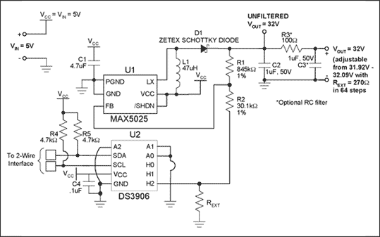
The example circuit uses the MAX5025 boost converter in conjunction with the DS3906 to provide up to 36V and 120mW (maximum) output.
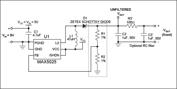
Fixed output DC-DC converter The typical application circuit shown in Figure 1 comes from the MAX5025 data sheet. In this circuit, the output voltage VOUT is determined by the ratio of fixed resistors R1 and R2. The two resistors of the voltage divider feedback the output voltage to the FB pin to form a closed-loop system. When the VOUT output is equal to the desired voltage, the system is in a stable state, and the voltage divider formed by R1 and R2 feeds back the 1.25V voltage to the FB pin. When VOUT is lower than the desired voltage (the voltage fed back to FB (VFB) is lower than 1.25V), the DC-DC converter will output extra energy until FB reaches 1.25V. Equation 1 is derived from the MAX5025 data sheet, and VOUT is calculated to obtain Equation 2, where VREF, the regulation point of FB, is equal to 1.25V in MAX5025.


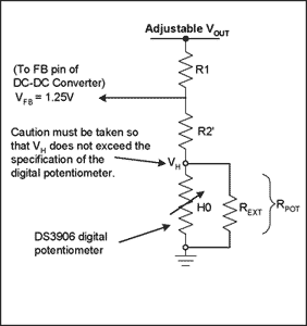
Figure 1. Fixed output, step-up DC-DC converter feedback loop to add a digital potentiometer. The circuit in Figure 1 provides a variety of ways to increase the digital potentiometer. This article focuses on the voltage divider structure shown in Figure 2.

Figure 2. Schematic diagram of feedback loop with digital potentiometer
The circuit shown in Figure 2 can accurately control the output voltage of the DC-DC converter to obtain the required voltage.
Equation 2 can be changed to:
 Some assumptions need to be made when calculating the initial design: VREF = VFB = 1.25V; when the potentiometer is placed in the middle position (position 20h), the expected output voltage is 32V; DS3906 is used in conjunction with an external resistor to achieve a linear response.
 The application note DS3906 resistance calculator and the Excel spreadsheet in the appendix of this article describe how to select the external resistance of the DS3906. For the circuit shown in Figure 3, resistor H2 is used in conjunction with an external resistor of 270Ω. The intermediate resistance value used in conjunction with an external resistor is 200Ω, which is used to calculate R1 and R2 in the MAX5025 circuit.
Assuming R2 is equal to 9.8kΩ, we can get the required R1 resistance value according to Equation 3. The calculated value of R1 is 246kΩ.
The resistance data sheet provided in this application note can help calculate the voltage range for this particular structure. The resistance data sheet shows that the output voltage can be precisely adjusted, allowing users to use different R1, R2 and external resistors (in parallel with H2).

Figure 3. Final circuit conclusion using the DS3906. This application note provides a solution for accurately adjusting the output voltage of a step-up DC-DC converter with a digital potentiometer. This article only gives an example of using the MAX5025 and DS3906 to obtain a 32V output, but the conclusions obtained in this article are applicable to any other potentiometer / converter, and other values ​​of output voltage can be obtained.
Adjustable Aluminum Laptop Stand,Laptop Stand Aluminium Adjustable Portable,Aluminum Laptop Stand Adjustable Height,etc.
Shenzhen Chengrong Technology Co.ltd is a high-quality enterprise specializing in metal stamping and CNC production for 12 years. The company mainly aims at the R&D, production and sales of Notebook Laptop Stands and Mobile Phone Stands. From the mold design and processing to machining and product surface oxidation, spraying treatment etc ,integration can fully meet the various processing needs of customers. Have a complete and scientific quality management system, strength and product quality are recognized and trusted by the industry, to meet changing economic and social needs.

Adjustable Aluminum Laptop Stand,Laptop Stand Aluminium Adjustable Portable,Aluminum Laptop Stand Adjustable Height
Shenzhen ChengRong Technology Co.,Ltd. , https://www.dglaptopstandsupplier.com