In modern industrial control, the most commonly used human-machine interface still uses a combination of keyboard and liquid crystal. To replace the previous human-machine interface interface, there are still some problems. In practical applications, the touch screen is generally designed for the programmable controller PLC, so the DSP and the touch screen cannot communicate directly, and the corresponding communication program must be developed according to the communication protocol of the touch screen. This paper studies the communication method of touch screen and DSP based on MODBUS protocol. The DSP uses TI's TMS320F2812, and the touch screen uses the LEVI700L of the control technology.
1 DSP and touch screen hardware circuit connection
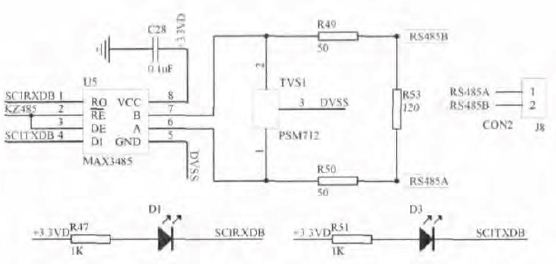
TI's TMS320F2812 chip has two SCI modules, SCIA and SCIB. According to different needs, these two serial ports can be designed and converted into RS232 and RS485 respectively. In this paper, RS485 is used to realize serial communication between DSP and touch screen. RS485 communication has the advantages of anti-electrical interference and long transmission distance compared with RS232 communication. Therefore, in the industrial control field, RS485 serial port and touch screen LEVI700L are used for communication. As shown in Figure 1, the SCIB port is designed as a half-duplex RS485 interface through the MAX3485 chip, that is, data can be transmitted in two directions, but cannot be transmitted at the same time. In the figure, the RE and DE pins are the transmit and receive enable terminals. The DSP controls the enable to be 1 or 0 by setting the pin PWM2 (A1) port to a general-purpose digital I/O port, that is, receiving or transmitting. The A and B pins are connected to the RS485 receiving end RS485A and the transmitting end RS485B through the electrostatic protection chip PSM712. The D1 and D3 LEDs in the figure are intended to monitor that the DSP is accepting or transmitting data.
The touch screen LEVI700L has a DB9 serial port and supports RS232/RS485/RS422, of which 2, 3, 5 are used for RS232 communication and 1, 6 are used for RS485 communication. In this design, the communication between DSP and touch screen adopts RS485. Therefore, it is only necessary to connect RS485A in Figure 1 with the 1 pin of the DB9 port of the touch screen, and RS485B can be connected to the 6 pin.

Figure 1 RS485 serial communication circuit design
2 Communication program design based on MODBUS protocol
2.1 Master-slave programming method of MODBUS protocol
The touch screen and DSP communicate according to the MODBUS protocol, the touch screen is used as the master station, the DSP is used as the slave station, and the serial port connection is RS485. The communication between the touch screen and the DSP is initiated by the touch screen. The DSP uses the interrupt mode to respond to the data sent by the touch screen. In the non-communication situation, the DSP can do more work. When the touch screen has data sent to the DSP, the DSP receives the interrupt, and the DSP enters the receive interrupt service subroutine. At this time, the touch screen sends to the DSP a complete data frame, which contains at least 8 bytes of data length, and is completely read. After taking this set of data, the DSP processes it. First, the slave station number is matched (in this paper, the DSP station number is set to 07). If the match is unsuccessful, the DSP does not respond to the touch screen query. The DSP does not send back any information. If the match is successful, the CRC check is performed. If the CRC check is wrong, If the query fails, the data information is not returned. If the CRC is correct, the next command is parsed and returned to the data information corresponding to the touch screen.
The following briefly describes how to read several analog quantities from the DSP and display them on the touch screen. The function code for reading the readable and writable analog registers is 03.
The command sent by the touch screen is: [Device Address] [Function Code 03] [Start Register Address High 8 Bits] [Low 8 Bits] [Read Register Numbers High 8 Bits] [Low 8 Bits] [CRC Check Low 8 bits] [High 8 bits of CRC check].
Example: 07 03 00 03 00 02 34 6D. This command shows that two analog quantities are to be read from the DSP's start address, 00 03.
At this point, if the device address matches and the CRC is correct, the DSP will return data to the touch screen.
The data returned by the DSP is: [Device Address] [Function Code 03] [Number of Bytes Returned] [Data 1] [Data 2]...[Data n] [Lower 8 bits of CRC check] [CRC checksum High 8 digits].
For example, the data returned in response to the above command is: 07 03 04 00 10 0020 9C 2E. The returned analog quantities are 16 and 32.
2.2 Touch screen introduction and configuration screen design
The touch screen LEVI700L is a 7-inch true color TFT produced by Weikong Technology. The motherboard specifications are: RISC CPU 400MHz, 128M Flash, 64DDRAM. It has a DB9 serial port that supports RS232/RS485/RS422 communication, and includes a USB Host and a USB Slave.
The touch screen LEVI700L comes with LEVI Studio configuration software, user-friendly, easy to operate, and supports offline and online simulation. This paper takes the application of touch screen in high-power thyristor rectifier controller as an example to illustrate the screen design of touch screen. There are main interface, real-time curve viewing setting screen, parameter adjustment screen, working mode query screen, and Figure 2 shows the main interface and real-time curve query screen. The communication port can be configured to connect the touch screen with the DSP and other controllers, and the corresponding communication protocol can be selected. The Modbus protocol is adopted in this design. The serial port parameter is set to baud rate: 38400Kbps, stop bit: 1 bit, data bit: 8 bits, no parity. You also need to configure the address of each component. The feedback voltage and current view in Figure 2 is a digital input/display component. The read address is edited according to the MODBUS protocol, and the data is read using function code 3. From the command format of the data sent by the touch screen in the previous section, it is necessary to set the station number and register type of the DSP and the start address.

Figure 2 touch screen screen design
2.3 Slave DSP Programming
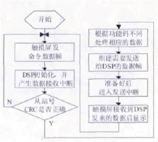
If the touch screen and DSP communication are successful, the serial port parameter setting must be consistent with the touch screen when the serial port of the DSP is initialized, that is, the baud rate: 38400Kbps, stop bit: 1 bit, data bit: 8 bits, no parity. Once the two communication is successful, the touch screen will send corresponding data commands to the DSP according to the component settings. As shown in the feedback voltage and current in Figure 2 above, the data read from the DSP needs to be displayed on the touch screen, and the command will be sent: 07 03 00 03 0002 34 6D. The processing after the DSP receives the command data is shown in Figure 3.

Figure 3 data communication flow chart
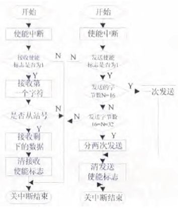
As can be seen from Figure 3, the programming of the DSP mainly includes initialization, receiving and transmitting interrupt subroutine, MODBUS frame parsing, processing and response subroutine, and CRC code verification subroutine. The flow chart of receiving and transmitting the interrupt subroutine is shown in Figure 4.

Figure 4 Receive and send interrupt subroutine flow chart
Elf Bar Pi9000 Review,Elf Bar Pi 9000 Einweg,Elf Bar Pi9000 Archiv,Elf 9000 Crystal Crowns
Longhua Manxueling Trading Company , https://www.mxlvape.com