Abstract : The author designed an instrument panel with integrated TPMS function for an electric vehicle. The TPMS receiver is implemented on the instrument panel in the form of a daughter board, which reduces the cost and inconvenience of independent installation, and can be easily installed and disassembled. Meet the requirements of different electric vehicle configurations. According to the working principle of TPMS and instrument panel and its integration method, the system structure, TPMS antenna design and instrument panel software design are analyzed. The TPMS transmitter is designed by SP37, and the problem of emission efficiency and service life is solved by the unique antenna design. The problem of smooth operation of the instrument panel pointer is solved by designing an adaptive control algorithm.
This article refers to the address: http://
The instrument panel is a multi-faceted car information display platform. It is a window for information exchange between the driver and the car. The electric vehicle instrument panel is a high-tech product that adapts to the electronic, digital and information development of electric vehicles. The information display platform displays the specific information of other electric vehicles such as vehicle speed, gear state, motor speed, motor state, battery pack status, etc., and realizes functions such as motor fault alarm, battery pack low voltage, and unbalanced alarm. TPMS (TirePressure Monitoring System) is a tire pressure monitoring system for real-time automatic monitoring of tire pressure and temperature during driving to ensure driving safety. It is an active safety component of automobiles. Currently widely used is the direct TPMS, which directly measures the air pressure of the tire using a lithium battery-powered pressure sensor installed in each tire, and transmits it to the receiver and monitor mounted on the bridge through radio frequency modulation. on. Due to the limitations of the structure and interior of the car, the installation position of the TPMS receiver and monitor becomes a difficult problem. There are currently two solutions, one is battery-powered or independent receiver and monitoring powered by car cigarette lighter. One is to integrate the receiver and monitor into a navigator or multi-function interior mirror or dashboard. In the first way, because the installation position is not fixed, there is a safety hazard during driving, and it will bring certain cost problems, but because of the strong independence, it can be applied to various models; the second way is fixed in installation position and can be reduced Cost, but needs to be customized to meet the integration requirements, not applicable.
This paper integrates the TPMS receiver in the form of a daughter board in the instrument panel, realizes the temperature and pressure receiving of the tire on the instrument panel, and displays and alarms the temperature and pressure of the tire through the instrument panel LCD, LED and buzzer to avoid TPMS receiving. Independent design and installation of the monitor and monitor. At the same time, the TPMS receiver can be easily loaded or unloaded according to the requirements of different models.
1 system structure
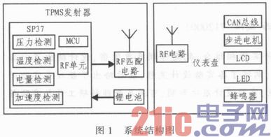
The system consists of two parts: TPMS transmitter and instrument panel. The MEMS chip of the transmitter is the core of the TPMS system. This solution uses Infineon's SP37 to design the TPMS transmitter, which is responsible for the detection of air pressure, temperature, power and acceleration. The data is sent to the receiver via wireless modulation. The collection and display of information is the core function of the instrument panel. Its display interface includes stepper motor and its pointer, LED, LCD and buzzer. The instrument panel integrates TPMS receiver in the form of daughter board to realize tire temperature on the instrument panel. Pressure receiving, data display and alarm of tire temperature and pressure through LCD, LED and buzzer to avoid independent design and installation of TPMS receiver and monitor. When the temperature or pressure of a tire is lower than a certain threshold, it can be alarmed by LED and buzzer sound and light. The mode button on the instrument panel can be used to check the temperature and pressure of the four tires, and it can be convenient according to the different requirements of different models. Load or unload the TPMS receiver. Its system structure is shown in Figure 1.

2 TPMS transmitter design
This solution uses Infineon's SP37 to design the TPMS transmitter as a MEMS chip that integrates the tire pressure sensor, MCU and RF transmitter. The SP37 performs the detection of air pressure, temperature, power and acceleration, and transmits the data to the receiver through wireless modulation. The specific function design part will not be repeated here. The article focuses on the antenna design points of the transmitter.
The antenna design of the transmitter is the key to the transmitter design, which determines the accuracy and real-time performance of the entire TPMS system, and also determines the life of the transmitter. If the transmitter antenna is not properly designed, the built-in tire pressure monitoring transmitter will improve the accuracy and real-time of the system by increasing the frequency of transmission, which will greatly consume the battery power and thus reduce the service life.
In this paper, wireless data transmission is realized by using a radiating metal plate shaped antenna. The length is close to 1/4 wavelength of the transmitter's wireless transmission frequency. By changing the thickness, shape and length of the transmitter metal piece antenna, the wireless transmission efficiency is improved and the transmission power is reduced. To extend the life of the transmitter battery, the metal piece antenna is directly injected into the transmitter housing, and is placed into the transmitter housing. Only the transmitting end and the grounding end of the antenna are connected to the circuit board, thereby reducing the thickness of the transmitter. And reduce the production cost, the antenna itself is covered by the outer casing plastic, can withstand the high temperature and high pressure inside the tire, and will not be deformed by the high-speed rotation of the tire, and has high reliability and stability.
3 dashboard design
The workload of automotive electronic electronic control unit software design accounts for 80% of the entire product design. Therefore, the paper focuses on the software design points of the instrument panel. Stepper motor control is the core function of the meter's meter display. The control algorithm is an example to introduce the software design of the dashboard.
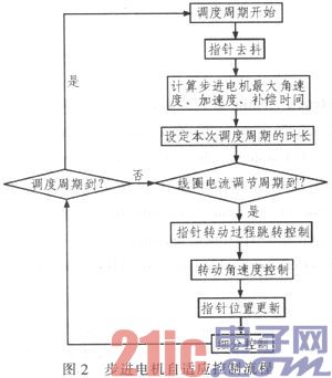
The instrument panel designed in this paper uses the stepper motor to drive the pointer to display the speed, working current and battery voltage. Since the stepping motor has the minimum step angle limitation and there is no position feedback, it is easy to appear jitter, overshoot, and out of step. The information indicates inaccurate series of problems. This paper uses the subdivision technology and acceleration and deceleration control technology on the underlying control to realize single-step and single-segment control of the stepper motor at the micro level, and the basis of the underlying control technology. The adaptive control algorithm is further designed to realize the continuous control of the stepping motor on the long-term span, and ensure the smooth running of the various pointers of the stepper motor type vehicle dashboard in various working periods and under various working conditions. The specific algorithm is designed as follows:
Firstly, according to the minimum subdivision granularity requirement of automotive instrumentation application, the subdivision control table of the sinusoidal law change of the stepping motor coil current is designed, and the subdivision control of the bottom stepping motor is realized by adjusting the index step of the control table; in the pointer scheduling control, The scheduling period is divided into variable time slots to control the hands in different periods. The rotation mode of the design pointer in a single scheduling period is four stages: acceleration start, constant speed running, deceleration stop, and inertia elimination. By designing the rotational angular velocity control, the pointer position update, the coil current adjustment step, the operation scheduling cycle duration, the starting acceleration, the stop deceleration, and the inertia elimination time, the smooth start and stop of each pointer of the automobile instrument panel is realized. Rapid response to fast-changing information and smooth reflection of slowly changing information allows quick start and smooth stop and no jitter at low speeds. The algorithm flow is shown in Figure 2.

4 Conclusion
This paper analyzes the system structure of the electric vehicle instrument panel integrated with TPMS function, introduces the antenna design of the TPMS transmitter, and analyzes the design of the adaptive control algorithm of the instrument panel stepper motor. The instrument panel is loaded and tested, and the operation is stable and functional. Reliable, it has entered the stage of small batch pre-production and has high practical value.
110KV-220kv Oil Immersed Transformer
110Kv-220Kv Oil Immersed Transformer,Anti - Interference 110Kv Transformer,Low Loss 110Kv Oil-Immersed Transformer,High Load Capacity 110Kv Oil-Immersed Transformer
Tianhong Electric Power Technology Co., Ltd , https://www.tianhongtransformer.com