After dismantling, it can be seen that the PIN type solid-state laser radar has a standard mass production component in addition to the lens, the threshold is very low, and the cost is not high, and the conventional low-pixel camera can be replaced in the future. But compared with the camera, the laser radar can work all day and all day, rain and snow, smog, day and night can be competent.

LeddarTech is a start-up from the National Institute of Optics, Quebec, Canada, with a total financing of 120 million US dollars. The investors include the world's three major TIer1 Magna, Delphi, Marelli, the world's largest optoelectronic component manufacturer Osram, large mixed-signal semiconductor manufacturer IDT Wait.
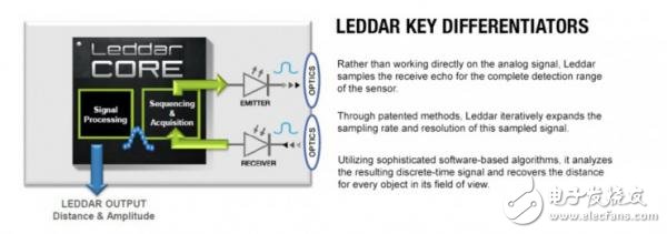
LeddarTech is not intended to provide laser radar products, but to provide one of the key components of solid-state laser radar: signal processing integrated circuits.
However, in order to promote its integrated circuits, LeddarTech has introduced a suite of solid-state lidars, and kits without MEMS mirrors cost less than $600.
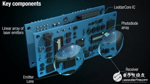
The above picture shows the LeddarTech solid-state laser radar. The laser emission array emits multiple sets of lasers. The PIN-type photodiode receives the light reflected from the laser. Similar to the principle of CCD or CMOS image sensor, a 3D image is finally obtained.
The precise distance between the object in the image and the radar can be obtained by simple calculation. At the same time, according to the value of the laser reflection intensity, common objects such as pedestrians, roads, concrete buildings, street lamps, grass, and MEMS mirror deflection can be easily identified. The laser beam is scanned against the object.
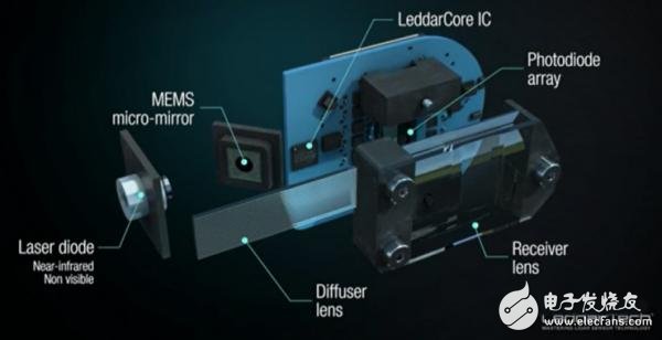
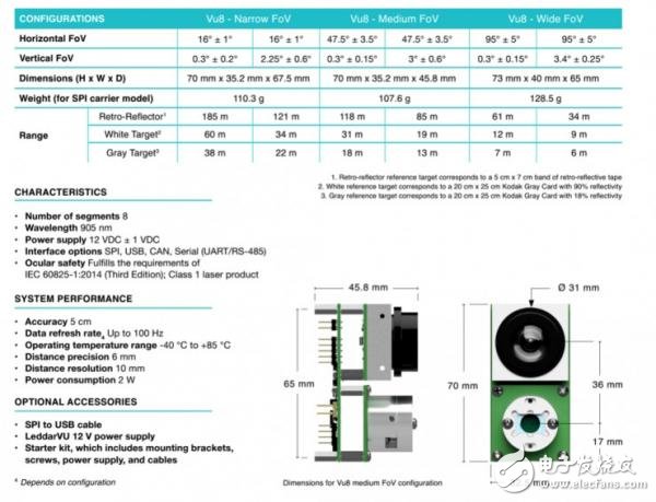
The LeddarVu8 laser radar is disassembled this time. The parameters of the LeddarVu8 laser radar are as follows:
After more than a decade of research and development, LeddarTech technology has matured to include a variety of commercial solutions such as Advanced Driver Assistance Systems (ADAS), traffic management, navigation and positioning, and level measurement.
LeddarTech has the key requirements for system development and integrators in developing laser radar applications: small size, low cost, low power consumption, high reliability, ruggedness, and adaptability.
Launch section: optical lens
The laser emitting lens portion is a combination of a collimating lens and a diffractive lens. Reflective and transmissive collimating mirrors are used in the beam delivery system to maintain the collimation of the beam between the laser cavity and the focusing optics.
Reflective collimators typically use a copper full mirror, while transmissive collimators use a zinc selenide lens. The diffraction grating lens substrate is lithographically etched with different thicknesses of the diffraction layer, and the light of different wavelengths or intensity is imaged at different positions by the diffraction relationship, thereby realizing the light splitting effect. It acts like a photonic router that combines photons into a variety of shapes.
As the laser beam passes through the microstructure of the laser diffraction plate, the photons will be reoriented by various shapes on the laser diffraction plate, similar to multi-line scanning of a rotary lidar.
The substrate of the diffraction grating is a glass of low expansion coefficient or fused silica, which is plated with aluminum and then engraved with parallel lines on the aluminum film. Diffraction gratings are extremely precise and difficult to manufacture and are commonly used on astronomical instruments.
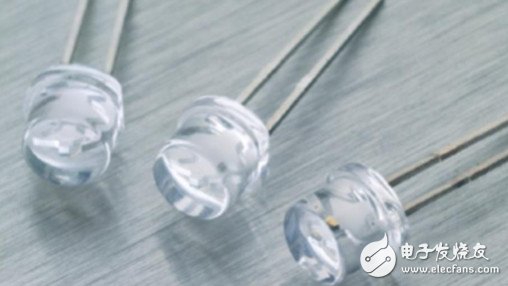
The laser diode for the launch section is supplied by Excelitas Technologies, one of the world's largest civilian laser diode companies with annual revenues of approximately $700 million and headquartered in Massação, USA. The laser diode model is TPGEW1S09H and belongs to the 225 micron series.

Excelitas Technologies is designed with metal-sealed inner packaging and plastic capsule packaging, which is much cheaper than industrial lasers and is suitable for mass production.
The TPGEW1S09H uses a GaAs epitaxial wafer and uses an InGaAs excitation layer. An 905 nm infrared laser is used.
Receiving part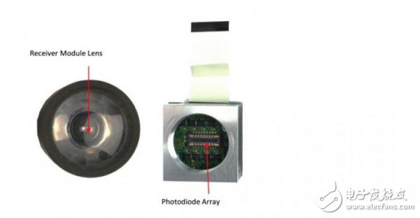
The receiving part is mainly a receiving lens and a photodiode array, and the receiving lens looks like a general focusing glass lens.
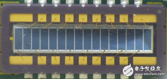
The photodiode array is the S7509 of Hamamatsu, Japan. The parameters are as follows:

The S7509 is available in a chip package and can be reflow soldered or SMT mounted, making it ideal for mass production. Dark current is relatively small and signal to noise is relatively high. Hamamatsu also has linear APD arrays and single photon array products.
Circuit part: motherboard, launch board and receiver board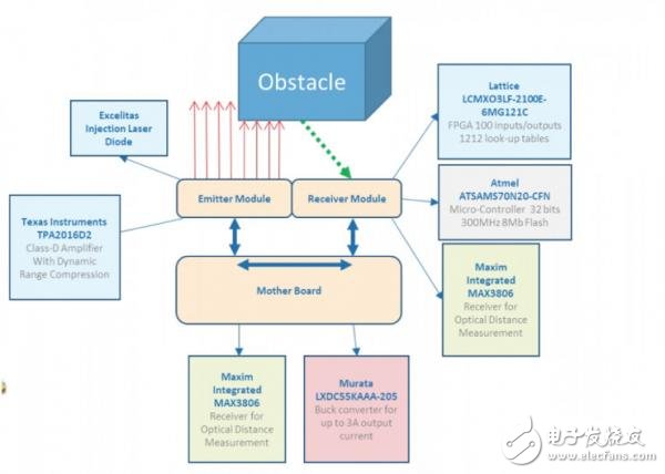
There is a Class D power amplifier from Texas Instruments on the launch pad. This chip is generally used for audio amplification. It is a current design that pushes the current load of the speaker. It may be used to amplify the current to the laser diode. It is a strange design.
There are three main chips on the receiving board, including a PLD from LatTIce. You can also call it FPGA, the model is LCMOX3LF-2100E-6MG121C.
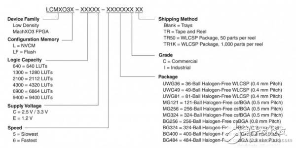
As can be seen from the above figure, this FPGA belongs to the MachXO3 series, which uses Flash to configure memory, and the logical computing compound is 2112, the fastest, 121-pin csfBGA package, commercial-grade products.
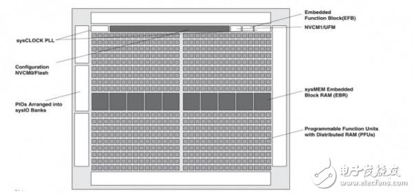
The figure above shows the internal frame of the LCMOX3LF-2100E-6MG121C. The biggest difference from the general FPGA is its built-in PLL phase-locked loop circuit. PLL (Phase Locked Loop): It is a phase-locked loop or a phase-locked loop. It is used to uniformly integrate the clock signal to make the high-frequency device work normally, such as accessing data in memory.
The PLL is used in feedback techniques in the oscillator. Many electronic devices work properly and usually require an external input signal to be synchronized with the internal oscillating signal. The general crystal oscillator can't do very high frequency due to process and cost. When high frequency application is needed, there is a corresponding device VCO, which is converted into high frequency, but it is unstable, so the phase-locked loop can be used. A stable and high frequency time pulse signal is achieved.
For pulsed lidars, high-precision clocks are the key to ensuring radar range accuracy. Leddar Tech does not currently have an ASIC, and can only be replaced with an FPGA.
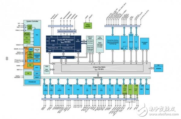
The receiver board has a Atmel Flash MCU, model ATSAMS70N20-CFN, which is an MCU with 1024Kbyte Flash and 384 MulTI Port SRAM. It is packaged in a 100-pin LQFP with built-in ARM Cortex M7 core. M7 is the most powerful ARM M series. One. The figure below shows the internal frame of the ATSAMS70N20-CFN.
There are eight MAX3806 receivers on the receiver board. The MAX3806 is an optical distance measuring device with a 60K or 30K switching impedance and an attenuator and preamplifier.
8 slices represent 8 receiving channels. The MAX3806, MAX4311, and MAX1446 work together. The MAX4311 is a MUX/AMP. The MAX1446 is a 10-bit, fully differential analog input ADC with a bit rate of 60Mbps, a precision reference voltage, and a 32-pin TQFP package for ultrasound image generation and CCD image generation. .
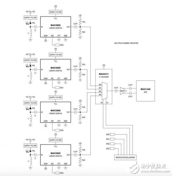
Flash solid-state laser radar can be seen as an image sensor. The above figure is an application example.
The main board is the power supply part. The core chip is a Murata LKDC55KAAA-205. This is a non-isolated DC/DC converter that can output 3A current and mainly supply the transmitting part.
summaryAfter dismantling, it can be seen that the PIN type solid-state laser radar has a standard mass production component in addition to the lens, the threshold is very low, and the cost is not high, and the conventional low-pixel camera can be replaced in the future. But compared with the camera, the laser radar can work all day and all day, rain and snow, smog, day and night can be competent.
It is conceivable that more solid-state laser radar products will appear in the future, and linear APD and single-photon laser radar with better performance have higher resolution, which may further squeeze the living space of the camera.
NLW-ECL Module (PM Fiber)
Nlw-Ecl Module Pm Fiber,1550 Nm Laser Diode Module,Pm Semiconductor Lasers Modules,1080 Nm Laser Module Tutorial
AcePhotonics Co.,Ltd. , https://www.acephotonics.com