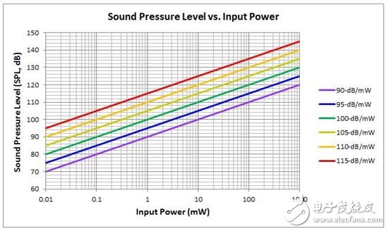
When we wanted to create an op amp for headset applications (the OPA1622 op amp was finally chosen), the first problem we needed to solve was to determine the power that the headset needed.
Think of headphones and speakers as transducers that convert input electrical power to audible output power. Like all processes, this will have an efficiency problem associated with electroacoustic conversion processes. As you may have thought, the efficiency of different headphone types is also different. In general, earbuds are less efficient than in-ear headphones.
Headset manufacturers typically express the efficiency of their products at a specific input power (usually 1mW) sound pressure level ([SPL] in decibels). For example, a headphone manufacturer may indicate the efficiency of their headphones as 100dB/wM, and you should read this value as "100dB at 1mW." By using the benchmark efficiency given by the manufacturer, you can use Equation 1 to calculate the SPL produced at other power levels:

In Equation 1, PIN represents the input power to the headphones, and η is the efficiency at the 1mW reference power level. Figure 1 shows the output SPL provided as the input power increases for a range of common headphone efficiencies.

Figure 1: The relationship between the resulting SPL and input power for different headphone efficiencies
The curve in Equation 1 and Figure 1 also includes an assumption that the operation of the driver in the headphone is linear. Of course, you can't always increase the input power of your headphones, and you want the output SPL to increase continuously (you can't do that). At high input power, the nonlinear effects within the driver itself will limit the maximum SPL.
Once you have established a SPL goal, determining the signal level requires only some basic electrical engineering equations (Equation 2 and Equation 3):


Both of these equations include the nominal headphone impedance, RHP, which is also specified by the headphone manufacturer. Headphones designed for portable electronic devices have a low impedance (down to 16Ω) because the low voltage signal on the headphones will still provide enough power. For headphones that are used in non-portable applications, such as headsets used in professional recording studios, their impedance may be as high as 600Ω.
Let us apply all this information to a design example and calculate the signal voltage and current required to reach a specific SPL for a pair of common flat magnetic ear headphones.

Table 2: Technical Specifications Target Values ​​for Design Examples
Using Equation 1 or Figure 1, first determine the input power required to achieve the SPL target value:

Next, calculate the voltage and current needed to provide this amount of power to the headphones:


In this example, the combination of low-impedance headphones and the low-efficiency and very loud maximum SPL target values ​​made our design team aware of the challenges that the OPA1622 design faces. Obviously, the amount of current that our amplifier needs to deliver to some headphones will be very large (as measured by the op amp standard). Under this premise, we turned our attention to the output circuit of the OPA1622. This circuit needs to be able to deliver large amounts of current without distortion.
DBS diode series patch rectifier bridge stack is composed of 4 rectifier diodes connected and packaged in the form of a bridge full-wave rectifier circuit, which belongs to a full bridge. There are four lead-out pins, the connection point of the negative poles of the two diodes is the "positive pole" of the DC output terminal of the full bridge, and the connection point of the positive poles of the other two diodes is the "negative pole" of the DC output terminal of the full bridge. Reverse repetitive peak voltage range: 50V~1000V, average rectified output current 0.8A~1.5A: forward non-repetitive surge current 30A (60Hz sine wave, one cycle, Tj=25°C). For specific parameters, please refer to the specification or consult online customer service.
DB-S diode,DBS Bridge Rectifiers,DBS SMD Bridge Rectifier Diode,Bridge Rectifier Diode DBS
Changzhou Changyuan Electronic Co., Ltd. , https://www.cydiode.com