Scientific research and design of equipment for research and development by researchers has been carried out in scientific research at the high-frequency end of the millimeter wave band. The signal source used in the study is a multiplier, and the drive multiplier is a Gunn effect diode oscillator or a reverse wave oscillator that can operate above 110 GHz. Signal detection is done by a custom narrowband detector or resonant mixer. During the course of the research, researchers were often limited by the narrow band characteristics of the test instrument.
In the study of the millimeter wave frequency range, spectral line analysis, molecular particle identification and material characterization are some of the most basic studies. Due to the effects of atmospheric effects on millimeter wave transmission, emerging millimeter wave applications include communications, transportation, scientific exploration, and homeland security.
In the early 1980s, a full-waveguide bandwidth vector network analysis (VNA) system capable of measuring signal absorption, reflection, and scattering characteristics within 110 GHz emerged. In the late 1990s, the capacity of the full waveguide bandwidth rose to 220 GHz. By 2002, the VNA system in the 220-325 GHz band was born. With the advent of the 325 GHz waveguide VNA system, researchers have begun to demand higher waveguide bands. It is this demand that has driven the development of frequency expansion modules at 500 GHz and higher.
The development of the 325 to 500 GHz VNA frequency expansion module presented here represents the highest frequency at which harmonic interference suppression can be achieved using a 20 GHz synthesizer. Since the harmonic interference in the waveguide passband has reached the point where it cannot be filtered out, the plan to achieve the next frequency band higher than 500 GHz with a practical multiplier scheme is affected.
WR-02.2 frequency expansion module structure
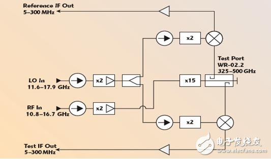
Figure 1 shows the structure of the WR-02.2 frequency expansion module. This architecture is consistent with the idea of ​​using a 20 GHz synthesizer as a local oscillator and RF input. At 20 GHz or higher, the synthesizer uses a double and/or triple multiplier to spread the synthesizer frequency range while its phase noise attenuation is 20 log (n). ). This structure does not have more advantages than the multiplier/amplifier in the millimeter wave frequency expansion module.
In order to reach the range of 325-500 GHz, the RF input frequency is amplified and multiplied by a multiplication factor of size 30. In order to reduce the amplitude fluctuation caused by the mismatch between the RF cable and the connection interface, an isolator is added to the RF multiplier/amplifier input. The multiplier/amplifier output signal produces an output frequency in the WR-02.2 band by driving a 15x multiplier chain. The 15x multiplier chain selected in the original design is optimized to minimize in-band harmonic interference with achievable filters. Using a 2x or 3x multiplier to form a low multiplier factor multiplier chain avoids some harmonic interference, but inter-multiplier signals require interstage amplification. There are few commercial products for W or higher-band amplifiers, and they are not without problems themselves, and more importantly, the complexity of the multiplication chain is increased. This 15x multiplication chain is measured by a calorimeter, and the output power can reach an average of -32dBm.
After the LO input frequency is amplified and multiplied by a net multiplier factor of 4, it is input to the millimeter wave mixer as the local oscillator input. An input isolator is placed at the input of the local oscillator frequency/amplifier to reduce the amplitude fluctuation caused by the mismatch between the local oscillator cable and the interface. After the output signal of the multiplier/amplifier is equally divided, it drives the next multiplier chain, and its output signal is supplied to the millimeter-wave local oscillator port as a reference signal and used to test the harmonic mixer. In order to optimize the match between the splitter and the multiplier, an isolator needs to be placed at the input of the multiplier. The frequency multiplier outputs a minimum output power of 10dBm in the WR-15 band, which is sufficient to properly bias the millimeter-wave harmonic mixer. This local oscillator chain topology is simple, which has been proven in the low millimeter wave band, and its inherent local oscillator phase continuity guarantees an optimum high noise level response.

The 325-500 GHz frequency signal is coupled to the millimeter wave harmonic mixer RF input through a 10 dB coupler. The millimeter-wave harmonic mixer IF output is optimized for 5 to 300 MHz output frequency. The multi-stage IF amplifier has a gain of A>50dB and can increase the peak IF output to -13dBm. The output power of -13dBm is chosen to prevent the internal network link saturation of the vector network analyzer from saturating while maximizing the dynamic range of the vector network analysis system. Depending on the selected millimeter wave vector network analysis system, it may be necessary to reduce the IF output power of -13dBm to avoid saturation of the millimeter wave test setting controller.
Solar Energy System,Portable Solar Panels,Solar Power System,Solar Pv System
suzhou whaylan new energy technology co., ltd , https://www.whaylan.com