(Transfer) In the fifth chapter of "Reuse methodology manual", mainly collected some specifications and guidance of HDL code. The purpose of following these specifications or guidelines is to make your code more readable, modifiable, and reusable; this should be the pursuit of all languages; for HDL code, the code should be suitable for synthesis and simulation.
Note: The following is not a golden rule, but if you can follow it, you can increase the efficiency of programming and improve the quality of the design.
1. General naming conventionPrinciple: Design your own naming conventions and document the rules; you need to be consistent in future designs.
Suggest:
Use lowercase letters to indicate all signals, variables, and port names;
Use capital letters to indicate constants and user-defined types (types);
Use meaningful names to represent signals, ports, functions, or parameters, such as ram_addr to represent RAM address bus.
Express a clock signal with a consistent name; such as CLK;
Represent a reset signal with a consistent name; such as RST;
An active low signal, adding "_b" or "_n" at the end of the name; if the reset signal is active low, it can be expressed as: rst_n;
Refer to the following:
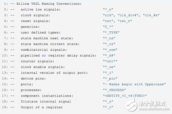
Express the bus in a consistent order, such as unified use in VHDL (x downto 0), Verilog HDL unified use [x:0];
Reasonable comments, for VHDL, reasonable description of process, funcTIon, type and subtype in the code
For ease of reading, try to keep the length of each line no more than 72 letters.
Use indentation to improve the readability of the code, and use the TAB key indented carefully, because different editors have different indentation definitions, 4 or 8 characters.
The order in which the ports are defined, only one port per line, first input port, then output port; the order can be: clk, rst, enable, other control signals, Date and address signals
Refer to the following:
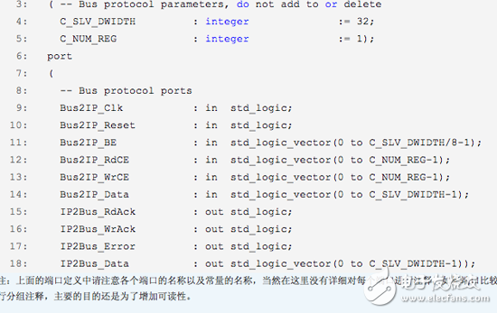
Note: Please note the name of each port and the name of the constant in the above port definition. Of course, each port is not commented in detail here; if the port is more and easier to group, please group the port, the main purpose Still to increase readability.
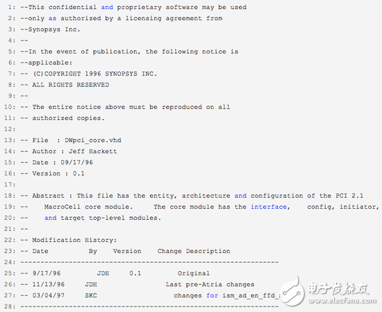
2. The contents of the source file header information (InformaTIonal Headers)Each source file should contain information about the file for the reader or future updates, so the header must contain the following:
Legal statement: confidentiality, copyright, restrictions on reproduction, etc.
file name
Author
Functional description and list of key attributes of the module
File creation date
Revised history: date, revision, modified statement
The header file is as follows:
Try to avoid using both rising and falling edge triggers in your design. If you can't avoid it, it's best to put the two flip-flops into different modules.
Avoid manually instantiating the clock buffer, and the synthesis tool will add it yourself;
Avoid the gated clock (Gated Clock), meaning that the clock signal reaches the clock input port of the flip-flop through a gate circuit, which brings some uncertain factors to the clock, resulting in jitter or delay;
Avoid internally generating a clock signal, and the internally generated clock signal will limit the online test of the design;
Data transmission across clock domains, for example: the design of a single-bit synchronizer, see the figure below;
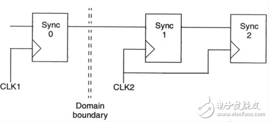
MulTIple-bit synchronizer can use reliable handshake circuit or mulTIbit coding scheme (this is not very understandable)
4. SynthesisAvoid the appearance of any latches in the design
Avoid feedback in combinatorial logic
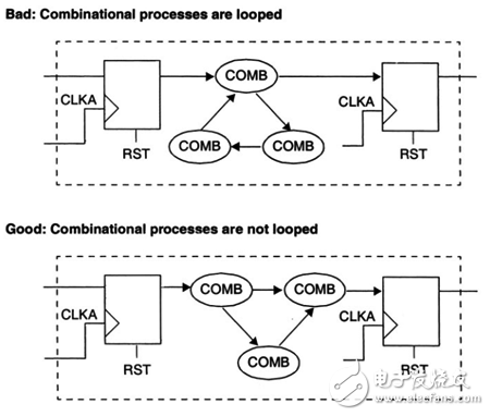
Define a complete list of sensitive signals, VHDL: process(sensitive list); Verilog: always(sensitive list);
5. Module PartitioningA good module division has the following advantages:
Better overall results
Reduce compilation run time
A simple integrated strategy can be used to meet timing requirements
Suggest:
Register the output of all modules

Put the relevant combinatorial logic into a single module. For example:
Bad example:

Good example:

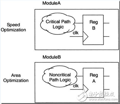
If two modules have different design goals, one required area, one required speed, it is best to separate the two modules, see the figure below.
Eliminate the instantiation of a gate-level logic in the top-level design, for example:
Bad example:
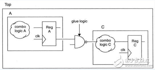
Good example:
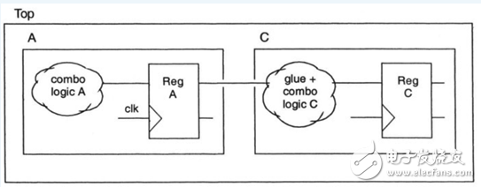
Lin Lin always said so much, chaotic, the content is basically excerpted from the book, there is no very fine place, just said how to do it, but absolutely did not say why. All of the above are the experiences in the book. The experience is still experienced by myself. If you encounter it, the experience will be profound. Learning while practicing, summing up and thinking, there will always be experience, there will always be experience, and the depth of thought will be improved.
tcl , https://www.tclgroupss.com