GTO is a current-controlled self-shutdown bipolar device. Like the BJT, which is a fully-controlled device, it turns on when the gate (called the base of the transistor) introduces a forward current, and it turns off when a reverse current is introduced, but it cannot turn off itself when the gate signal is removed like the BJT. That is to say, GTO is the same as the thyristor, once it is turned on, it can have the holding effect in the on state, and it will still be on without the gate current. So GTO is a kind of thyristor that must rely on the polarity change of the gate current to change the on-off state. The reverse gate current to turn off the GTO usually has to reach 1/5 to 1/3 of the anode current, so the control of the turn-off process is far less economical and convenient than BJT. However, compared with the power handling capacity of a single tube, BJT is far inferior to GTO. GTO has played an important role in the history of large-capacity power electronic converters.

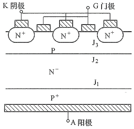
Figure 1 Typical GTO structure diagram
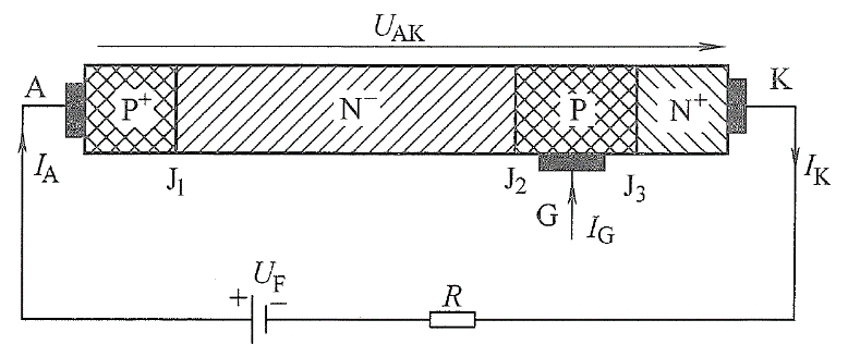
The basic structure and basic working principle of GTO are the same as ordinary thyristors, but for the purpose of turning off the gate and improving the control ability of the gate, the relative area of ​​the P area (in contact with the gate) to the N+ emitter area (in contact with the cathode) is enlarged. , And divide the N+ area into zeros, and place it around the P area. These separated tiny N+ regions form all the thyristor units of the GTO die by sharing the P, N, and P+ regions. Each unit thyristor has its own independent cathode, which is usually connected in parallel to the same cathode block by crimping. The anode of GTO is usually connected together with a certain shape of metal grid. Figure 1 shows a schematic partial cross-sectional view of a typical GTO die. From the process point of view, the manufacturing of GTO is much finer and more complicated than the manufacture of thyristors, but GTO has the same simplified structure as thyristors, as shown in Figure 2.

Figure 2 Simplified thyristor structure and external circuit connection
GTO is also turned on partially first, and then expanded to achieve full turn-on. The slight difference is that the conduction of GTO occurs in each unit at the same time, expanding from the edge to the center in each unit at the same time, while the ordinary thyristor is turned on as a complete large unit, and the expansion area is much larger.
As far as each unit is concerned, the turn-on process of GTO is exactly the same as that of thyristor, and it also depends on the gate electrode to inject forward current to meet the turn-on condition:

The turn-off process of GTO is also performed in each unit at the same time, but its turn-off method and principle are different from thyristors. It is turned off by the extraction of holes in the P region by the reverse bias gate. For thyristor-type devices, the unbalanced carriers in the P region are a necessary condition for maintaining conduction. When the holes in the unbalanced carriers flow away with the negative gate current, the positive bias conditions of the J2 junction and the J3 junction are weakened, and the injection efficiency of electron injection from the N+ region to the P region through the J3 junction decreases accordingly until it is completely lost. The positive bias condition stops the injection of extra electrons. Of course, this process is also gradually advancing from the edge to the center in each unit. The concentration of electrons and holes gradually decreases from the outside to the inside, and the J2 junction gradually resumes its blocking effect from the outside to the inside. When the electrons and holes are reduced to a certain limit, it is difficult for the injection effect unit of the J3 junction to maintain the entire conduction state, so the J2 junction restores its reverse bias state, and the GTO restores the reverse blocking ability of the J2 junction in each unit. When it is turned off.
It is not possible to control the turn-off of ordinary thyristors in the same way, because the structure of the two is different. The GTO adopts a structure in which the N+ area is surrounded by a P area, which can be regarded as an improvement of the thyristor structure. As mentioned before, the first thing to turn off is to destroy the excess electrons and holes in the P area and draw the holes from the gate. Since the gate and the cathode are on the same side of the device, the gate current is basically the lateral current determined by the lateral resistance of the P area, and the P area is very thin, and the thickness is generally only tens of μm. When the gate-cathode distance is long, The lateral resistance must be too large, so the gate-cathode structure of an ordinary thyristor cannot draw a large enough hole current. The gate-cathode structure of GTO greatly shortens the distance between the two, and thus can effectively extract holes.
As an important part of IGCT, gate commutated thyristor (GCT) can be regarded as an improved GTO, and its basic operating principle of opening is basically the same as that of thyristor. The turn-off can be seen as a GTO that completely changes the cathode current to the gate, which requires the cooperation of the peripheral auxiliary MOSFET. IGCT can be seen as a composite device in which two devices are mixed outside the chip.
Focusing on the development and production of Wireless Charging products that make life easier.
Supply various wireless charger including multifunctional Wireless Charger, Car Wireless Charger, Magnetic Wireless Chargin, Wireless Charging Mouse Pad, etc.
We help 200+ customers create custom wireless charging products design for various industries.
Manufacturing high quality products for customers according to international standards, such as CE ROHS FCC REACH UL SGS BQB etc.
Wireless Charging Pad,Wireless Phone Charger,Wireless Car Charger,Bluetooth Charger
TOPNOTCH INTERNATIONAL GROUP LIMITED , https://www.itopnoobluetoothes.com