Binary numbers are used for calculations without exception, but they are usually read and written in octal and hexadecimal. For computer technology professionals, it is okay to understand the meaning of these numbers, but it is not so easy for non-professionals. Since the most familiar number system in daily life is decimal, a binary decimal code, called BCD code, is specified, which is a decimal number expressed in binary.
BinaryBinary is a number system widely used in computing technology. Binary data is a number represented by two numbers 0 and 1. Its cardinality is 2, the carry rule is "every two into one", and the borrowing rule is "borrowing one and two", discovered by the 18th century German mathematical philosophy master Leibniz. Current computer systems use essentially binary systems, and data is stored primarily in the form of complements in the computer. The binary in the computer is a very small switch, with "on" to indicate 1, "off" to indicate 0.
The invention and application of computers in the 20th century, known as one of the important symbols of the third technological revolution, because digital computers can only be identified and processed by '0'. The code consisting of the '1' symbol string. Its operation mode is binary. In the 19th century, the Irish logician George Boolean thought of the process of thinking about logical propositions into some algebraic calculus for the symbol "0''. ''1'', binary is the carry system of the binary carry. 0, 1 is the basic operator Because it only uses 0, 1 two-digit symbols, it is very simple and convenient, and easy to implement electronically.
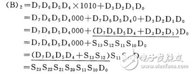
8421bcd code conversion binaryDesigned with MSI devices. Let the two 8421BCD code be D7D6D5D4D3D2D1D0 converted B code is B685B4B3B2B1B0

In the above formula, the horizontal line portion can be realized by an MSI adder. S is the output of the adder. The subscript of the adder represents the module serial number and the output high and low bit numbers.
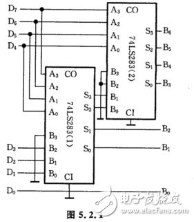
The logic diagram is shown in Figure 5.2.1.

[Solution 2]
VHDL design.
According to the above solution method, the structure description method can be adopted in the structure design of the VHDL program. The VHDL main program is as follows:
LIBRARY ieee;
USE ieee. Std_logic_1164. ALL; USE work. Components. ALL;
ENTITY xiti50 1 IS PORT(d:IN Std_logic_vector(7 downto 0);
b: OUT Std_logic_vector(6 downto 0));
END xiti501;
ARCHITECTURE xiti501_ar OF xitiS01 IS SIGNAL m:Std_logic_vector(3 downto 0);
SIGNAL n1n2: Std_logic;
COMPONENT v74x283 PORT(ab:IN std_logic_vector(3 downto 0);
Ci:IN std_logic;
s:out std_logic_vector(3 downto 0);
Co:OUT std_logic);
END COMPONENT;
BEGIN u1:v74x283 PORT MAP('0'&d(3 downto 1)d(7 downto 4)'0'mn1);
U2:v74x283 PORT MAP("00"&m(3 downto 2)d(7 downto 4)'0'b(6 downto 3)n2);
b(0)"=d(0);
b(2 downto 1)"=m(1 downto 0);
END xiti501_ar;
[Solution 1]
Designed with MSI devices.
Let the two 8421BCD codes be D7D6D5D4D3D2D1D0, and the converted B code be B685B4B3B2B1B0, then the horizontal line part of the above formula can be realized by an MSI adder, S is the output of the adder, and the subscript of S represents the module serial number and output level. Bit number. The logic diagram is shown in Figure 5.2.1. [Solution 2] VHDL design. According to the above solution method, in the structure design of the VHDL program, the structure description method can be adopted, and the VHDL main program is as follows:
LIBRARYieee;
USEieee. Std_logic_1164. ALL;
USEwork. Components. ALL;
ENTITYxiti501ISPORT(d:INStd_logic_vector(7downto0);
b: OUTStd_logic_vector(6downto0));
ENDxiti501;
ARCHITECTURExiti501_arOFxitiS01ISSIGNALm: Std_logic_vector(3downto0);
SIGNALn1, n2: Std_logic;
COMPONENTv74x283PORT(a,b:INstd_logic_vector(3downto0);
Ci:INstd_logic;
s:outstd_logic_vector(3downto0);
Co:OUTstd_logic);
ENDCOMPONENT;
BEGINu1:v74x283PORTMAP('0'&d(3downto1),d(7downto4),'0',m,n1);
U2:v74x283PORTMAP("00"&m(3downto2), d(7downto4), '0', b(6downto3), n2);
b(0)"=d(0);b(2downto1)"=m(1downto0);
ENDxiti501_ar;
Indoor Rental LED Display is hot selling product in the led screen market. We usually use Nova MSD300 sending card and MRV328 receving card, other controll system also can be accepted, like Linsin,colorlight and so on.....About the led lamp, we use kinglight led lamp, IC is ICN2038S, refresh rate is 1920hz. We also provide other option if the client need higher quality, like Nationstar led lamp and refresh rate can make 3840hz. This 500x500mm LED display panel can also can make curved led display, ±15° flexible curved option.
Application:
* Business Organizations:
Supermarket, large-scale shopping malls, star-rated hotels, travel agencies
* Financial Organizations:
Banks, insurance companies, post offices, hospital, schools
* Public Places:
Subway, airports, stations, parks, exhibition halls, stadiums, museums, commercial buildings, meeting rooms
* Entertainments:
Movie theaters, clubs, stages.
Indoor Rental LED Display,Advertising Led Display,Indoor Led Display,Rental Led Display
Guangzhou Chengwen Photoelectric Technology co.,ltd , https://www.cwstagelight.com