Today's various intelligent control systems are inseparable from the transmission of data information. Among them, wireless data transmission is a new transmission method that is different from traditional wired transmission. The system does not require transmission cables and has a low cost. Match the corresponding wireless communication interface circuit for the one-chip computer, can realize the wireless data transmission between the one-chip computer or between the one-chip computer and the computer. The commonly used wireless communication interface circuit is a circuit whose core is a wireless transceiver chip. When data is transmitted, necessary anti-jamming measures and identification measures are taken in the software design to effectively avoid interference and achieve satisfactory communication results. Based on the 89c2051 microcontroller, the wireless communication is used to identify the non-contact wireless identification device. The application can be embedded in the electric power management or gas charge system, or it can be used as an independent card reader to operate the IC card. Software can be applied to different industries.
1 How does the system work?This design uses a single-chip microcomputer as the core of readers and transponders. These two parts mainly use the LM567. This system is a small wireless identification device with a maximum operating distance of 70mm. The internal structure of the system is divided into radio frequency area and interface area: the radio frequency area contains the modem and power supply circuit, and is directly connected to the antenna; the interface area has a port connected to the microcontroller, and also has a transceiver connected to the radio frequency area, and can use a single-chip computer. The program stores three sets of E2PROMs for register initialization files, and a three-time data verification anti-error mechanism, anti-collision prevention anti-collision module, and a control unit. This is the core module for wireless communication between the reader and the transponder, and it is also the key to the design.
2 hardware circuit designThe wireless identification system device consists of a reader, a transponder, and a coupling coil (ie, antenna) 3 parts.
2.1 Reader Design
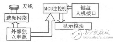
The basic circuit of the reader is shown in Figure 1. When there is a transponder close to the reader, the antenna in the reader constitutes an LC parallel resonant circuit, the frequency of which is the same as that of the transponder, so that under the excitation of the electromagnetic wave, the LC resonant circuit resonates, so that the high frequency signal The input to the LM567 for demodulation in the reader. The demodulated signal output is inverted with the above-mentioned one-chip computer coded signal, and finally is decoded and displayed by the single-chip microcomputer.
LM567 has dual functions of modulation and demodulation. The signal it mediated can be directly recognized by the SCM and sent to the digital control and displayed by the SCM.

Figure 1 Reader
2.2 Transponder Design
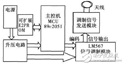
When the transponder is working, the data is coded by the 89c2051 microcontroller, then sent to the LM567 and modulated on the high-frequency carrier. The antenna coil connected to the output end continuously emits a set of fixed-frequency electromagnetic waves (145kHz). Near the reader, the reader recognizes and displays. Transponder hardware circuit shown in Figure 2.

Figure 2 Transponder
2.3 Design of Coupling Coils (ie Antennas)
The antenna is a type of energy converter. When transmitting, the transmitter's high-frequency current is converted into space electromagnetic waves; when receiving, electromagnetic waves intercepted from space are converted into high-frequency currents and sent to the receiver. Antenna design is an important part of designing a low-power, short-range wireless transceiver for radio frequency identification systems. A good antenna system can achieve the best communication distance. There are many kinds of antennas, and different applications require different antennas. In a low-power, short-distance RFID system, a reliable and inexpensive antenna system is required, and a coupled coil loop antenna is a relatively common one.
2.3.1 Analyzing the equivalent circuit of a loop antenna
The voltage and current of the loop antenna excitation point are linked by the input impedance of the loop, ie V=ZI0. In order to evaluate the capacitance Z'in for antenna resonance, the input impedance of the loop antenna must be determined; likewise, in order to evaluate the antenna efficiency and radiation resistance, the ohmic loss and other ohmic losses within the loop type conductor must also be determined.
2.3.2 Antenna Design Parameters
The loop antenna input impedance Zin can be given by:

In the formula, RR is radiation resistance; RL is ring-shaped conductor loss resistance; RX is extra ohmic loss resistance; LA is loop antenna inductance; L1 is toroidal conductor inductance.
Ring conductor loss resistance is:

In the formula, l is the length of the metal loop conductor, p is the perimeter of the cross section of the loop conductor, RS is the conductor surface resistance, u0 is 4π&Times; 10-7H/m; σ is the conductivity of the conductor; RL is in units of Ω. The extra ohmic loss resistance mainly comes from the equivalent series resistance on the capacitor CP:

2.4 Equivalent Circuit of Reader with Antenna
The conductor loop required to generate the alternating magnetic field is represented by the coil L1, and the series resistor R1 corresponds to the ohmic loss of the wirewound resistor in the conductor loop L1. In order to obtain a maximum current in the conductor loop L1 when the operating frequency of the reader is fTX, thereby generating a maximum magnetic field strength H, a series resonant circuit having a resonant frequency fRES=fTX is formed in series via the capacitor C1.
In FIG. 4, the transmitter output of the reader generates a high-frequency voltage u2, and the receiver is directly connected to the antenna coil L1. The total impedance Z1 of the series resonant circuit is the sum of the single impedances, ie:

2.5 Antenna Connection Matching Study
Depending on the frequency range used by the reader, different methods are used to connect the antenna coil to the output of the reader transmitter. The antenna coil is directly connected to the power output stage by power matching or fed to the antenna coil through the coaxial cable. The antenna coil L1 exhibits an impedance ZL within the operating frequency range of the RFID system. In order to achieve power matching with a 50Ω system, this impedance must be converted to 50Ω by a passive matching circuit, which can then be transmitted from the reader stage to the matching circuit with virtually no loss and no radiation through the coaxial cable.
3 debugging and testing3.1 debugging method
When the circuit is debugged, the oscillation frequency can be varied within 0101Hz to 500kHz. The oscillation frequency must be adjusted to achieve the best match with the carrier frequency of the LM567. Otherwise, the demodulation of subsequent circuits will be affected (for example, the oscillation frequency is too close to the carrier frequency of the LM567). It will directly affect the demodulation of the subsequent frequency, etc.) and the oscillation frequency of the microcontroller will also affect the output waveform. If the output is not a rectangular wave, it may affect the recognition of the signal by the microcontroller and make the response time longer or compile error, so the circuit debugging Very important. LM567 must realize debugging to the mutual modulation and demodulation smoothly, if the transmitter is working, and the receiver can't decode correctly, should adjust the resistance of the timing resistor R8, make it accord with the requirement. Since the LM567's oscillation frequency (center frequency) requires high precision, when adjusting the R8 resistance, the R8 resistance should be replaced with a 10kΩ multi-turn precision wirewound resistor. Each time this resistance is rotated, the resistance value changes by several tens of ohms and the precision is high. If this resistor is not available, ordinary trimming resistors can also be used instead but careful adjustments should be made. If the conditions permit, the frequency meter can be directly connected between the LM567 pin 5 of the transmitter and the ground, measure its oscillation center frequency, record the value, and then measure the receiver LM567 pin 5 frequency. If the center frequency of the receiver (refer to LM567) and the center frequency of the transmitter LM567 are different, adjust the R8 resistance value so that the center frequencies of the two audio decoders can be equal.
3.2 Test data
When testing the data, all 8-bit codes from 00 to FF are tested (4 bits are definitely not a problem), and the power supply power is calculated and measured several times. The distance of the coupling coil is tested for data transmission within a range of 1 to 6 cm, which ensures protection. 5cm data transmission is stable. The test data list is as follows.
Table 1 Test data list

According to the above experimental measurement results, it can be seen that this system achieves all the basic functions and most of the functions required by the problem, and has its own characteristics and functions. The performance is reliable and stable.
3.3 Analysis of test results
3.3.3 System Waveform Data Test
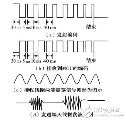
Take a top-down approach to debugging, that is, tune each module individually, then connect it into a complete system, and then perform overall debugging. The comparison of data transmission and reception signals is shown in FIG. 3 .

Figure 3 Comparison of data transmission and reception signals
3.3.2 Possible errors in the system itself
(1) External interference factors
The use of wireless transmission has a very serious drawback, that is susceptible to electromagnetic interference and transmission problems are not good, due to external high-frequency signals, metal and many other devices may interfere with electromagnetic waves, so the circuit will inevitably produce errors
(2) Distance interference factors
When the electromagnetic field propagates in the conductive medium, the amplitudes of the field quantities E and H decay exponentially with increasing distance. From the energy point of view, electromagnetic waves attenuate rapidly in good conductors, which attenuates the conductor surface to 1/e (about 3618%) of the surface, that is, the reason why the distance specified in the text is 5 cm is the reason for this, which is caused by distance factors. Garbled and unrecognizable codes are also one of the causes of errors.
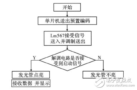
4 flow chartThe software programming uses the one-chip computer assembly language, the editing software is Keil51, gives the program flow chart to be shown as in Fig. 4.

Figure 4 program flow chart
5 ConclusionThe reader of this system can identify the presence or absence of the transponder in the range of 6cm. If the transponder is in the monitoring range, it gives a clear indication and reads the preset 4-digit code of the transponder, and then displays; The part of the device can also send a coded signal within the reader's identification range by setting a 4-bit code in the switch. At the same time, the reader also has the function of writing the code of the transponder, which is received and stored by the transponder. The key point in the design is to ensure the correct rate. The verification code can be added from the software to improve the reliability of wireless transmission.
We have been helping customers to complete the research and development and production of various types of battery protection boards, sourcing from around the world, creating the best supply chain system, and using high-precision surface mount technology to achieve product engineering and manufacturing services for high-end and high-quality customers.
BMS,BMS Battery Board,Solar Battery Board,Solar Cell Protection Plate,Battery Board Design
Huizhou Liandajin Electronic Co., Ltd , https://www.ldjpcb.com