First, briefly introduce the CAN bus, who invented the CAN bus, the history of the CAN bus, the development of the CAN bus, the application of the CAN bus, and these do not say. Here is my personal understanding, simply talk about CAN communication. The end of the CAN bus has no address (unless you define the address in the frame yourself). The CAN bus communication does not use an address. Instead of using an identifier, who is sent to whom, it is always sent to the entire network. Each node then has a filter that filters the identifiers of the propagated frames on the network, what kind of frames it wants, sets its own filters, and receives relevant frame information. What if two nodes send at the same time? This does not need us to worry, CAN controller will arbitrate by oneself, let high-priority frame start.
Then we can understand the CAN controller of stm32.

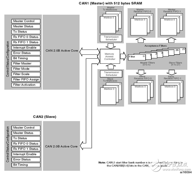
As shown in the above figure, stm32 has two can controllers, can1 (master), and can2 (slave), in which the filter settings are set by can1, and other operating modes, such as baud rate, can be set individually. Each controller has three sending mailboxes, two fifos, and three receiving mailboxes per fifo.
Send: Select an empty send mailbox, write the frame information to the register of the send mailbox, request to send, and the controller will send the frames in order according to the priority of the identifier.
Receive: If the identifier of the received frame can be filtered by a series of filtering tables, the frame information will be stored in the register of the fifo receiving mailbox.
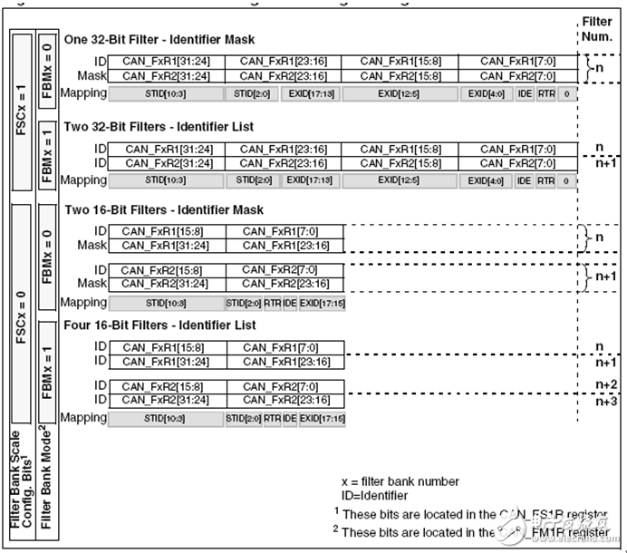
Filter: There are 28 filters in stm32f407. Each set of filters can be set to fifo0 or fifo1. Each set includes two 32-bit memories, which can be configured as a 32-bit identifier filter, or two 32-bit fully-matched identifier filters, or two 16-bit, bit-masked identifier filters, or four 16-bit, fully matched identifier filters. As shown below:

What I mean by exact match is that the identifier of the received frame must be the same as the corresponding bit of the filter in order to pass this filter. A bit masking function means a register identifier, a mask mask, and the bit of the identifier of the received frame corresponding to the bit with the mask mask of 1 is the same as the bit of the register corresponding to the identifier. Can pass.
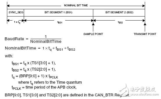
Transmitting a one-bit time and baud rate calculation:

The baud rate of CAN controller is determined by TS2[3:0], TS1[2:0] and BRP[9:0] of APB clock line and CAN bit timing register CAN_BTR, among them, TS1[2:0] It defines how many time units are occupied by time period 1, TS2[3:0] defines how many time units are occupied by time period 2, and BRP[9:0] defines the frequency division of APB1 clock.
PS: set the baud rate to 1M

Where Tpclk is the APB1 clock period, assuming
Tpclk = 1/42M
0≦TS1≦7
0≦TS2≦15
0≦BRP≦1021
According to the above data, there are
(TS2+TS1+3)(BRP+1)=42
Let BRP = 2, there is
TS2+TS1=11
Let TS1=8, TS2=3
Setup steps:
1. Set the interrupt priority grouping (if not set before), this is best set once at the beginning of a program.
2. Enable the relevant GPIO clock.
3. Select the alternate function of the relevant GPIO pin.
4. Set the related GPIO pin to multiplex mode.
5. Set the speed and mode of the related GPIO pins.
6. Set main control register MCR to enter initialization mode
7. Wait for initialization mode
8. Set the baud rate.
9. Other settings.
10. If an interrupt is to be used, enable the relevant interrupt response in the interrupt enable register IER.
11. If you want to use interrupts, set the relevant interrupt priority (NVIC_IP).
12. If an interrupt is to be used, enable the relevant interrupt (NVIC_ISER).
13. Set the main control register MCR to enter normal operating mode.
14. Set the FMR so that the filter group works in initialization mode.
15. Set the FMR CAN2SB to determine from which group the CAN2 filter group starts.
16. Set the working mode of the used filter group.
17. Set the bit width of the filter group used.
18. Divide (associate) filter groups for fifo0 and fifo2.
19. Disable the filter group used.
20. Set filter group identifier, frame type, etc.
21. Enable the relevant filter group.
22. Set the FMR so that the filter group operates in normal mode.
23. If you want to use interrupts, write interrupt service functions (function names are fixed).
24. Check which interrupt is in the interrupt service function.
25. Write corresponding service procedures.
Circuits See this blog: Gadgets - CAN Transceivers
program:
[plain] view plaincopy/************************************
Title: Exercises for CAN operation
Software Platform: IAR for ARM6.21
Hardware platform: stm32f4-discovery
Frequency: 168M
Description: Connect CAN1, CAN2 via hardware transceiver
A network of two endpoints
CAN1 cycle sends data frames
CAN2 Receive Filter Data Frame
Receive CAN2 with uart
Data frames sent to the HyperTerminal
Author: boat
Data:2012-08-14
*************************************/
#include "stm32f4xx.h"
#include "MyDebugger.h"
#define RECEIVE_BUFFER_SIZE 20
U32 CAN2_receive_buffer[RECEIVE_BUFFER_SIZE][4];
U8 UART_send_buffer[1800];
U8 Consumer = 0;
U8 Producer = 0;
U32 Gb_TImingDelay;
Void Delay(uint32_t nTIme);
Void TIM7_init();//timing 1s
U32 get_rece_data();
Void CAN_GPIO_config();
Void main ()
{
U32 empty_box;
SysTIck_Config(SystemCoreClock / 1000); // Set systemtick one millisecond interrupt
SCB-"AIRCR = 0x05FA0000 | 0x400; // Interrupt Priority Packet Preemption: Response = 3:1
MyDebugger_Init();
TIM7_init();
MyDebugger_Message( "testing....". )
Sizeof("testing.. ...")/sizeof(char) );
CAN_GPIO_config();
RCC-"APB1ENR |= ((1 "25"|(1 "" 26)); // Enable the CAN1, CAN2 clock
CAN1-"MCR = 0x00000000;
/*
Request to enter initialization mode
Disable automatic retransmission of messages
Automatic wake-up mode
*/
CAN1-"MCR |= ((1 "") | (1 "" 4) | (1 "" 5));
CAN1-"MCR &= ~(1 ""16);//At debugging, CAN works as usual
While(!(CAN1-"MSR & 0xfffffffe)) //waits to enter initialization mode
{
MyDebugger_LEDs(orange, on);
}
MyDebugger_LEDs(orange, off);
/*
Normal mode
Resynchronize jump width (1+1)tq
TS2[2:0]=3
TS1[3:0]=8
BRP[9:0]=2
Ps:
Tq = (BRP[9:0] + 1) x tPCLK,
tBS2 = tq x (TS2[2:0] + 1),
tBS1 = tq x (TS1[3:0] + 1),
NominalBitTime = 1 × tq+tBS1+tBS2,
BaudRate = 1 / NominalBitTime
Baud rate is set to 1M
*/
CAN1-"BTR = ((0, "30" | (0x01 "" 24) | (3 "" 20) | (8 "" 16) | (2 "" 0));
CAN1-"MCR &= ~(0x00000001);//normal working mode
CAN2-"MCR = 0x00000000;
/*
Request to enter initialization mode
Disable automatic retransmission of messages
Automatic wake-up mode
*/
CAN2-"MCR |= ((1 "") | (1 "" 4) | (1 "" 5));
CAN2-"MCR &= ~(1 ""16);//In debugging, CAN works as usual
While(!(CAN2-"MSR & 0xfffffffe)) //waits to enter initialization mode
{
MyDebugger_LEDs(orange, on);
}
MyDebugger_LEDs(orange, off);
/*
Normal mode
Resynchronize jump width (1+1)tq
TS2[2:0]=3
TS1[3:0]=8
BRP[9:0]=2
Ps:
Tq = (BRP[9:0] + 1) x tPCLK,
tBS2 = tq x (TS2[2:0] + 1),
tBS1 = tq x (TS1[3:0] + 1),
NominalBitTime = 1 × tq+tBS1+tBS2,
BaudRate = 1 / NominalBitTime
Baud rate is set to 1M
*/
CAN2-"BTR = ((0, "30" | (0x01 "" 24) | (3 "" 20) | (8 "" 16) | (2 "" 0));
CAN2-"IER &= 0x00000000;
/*
FIFO1 message registration interrupt enable
FIFO1 full interrupt enable
FIFO1 overflow interrupt enable
*/
CAN2-"IER |= ((1 "4"|(1 "5"|(1 ""6));
NVIC-"IP[65] = 0xa0; // Preempt priority 101, response priority 0
NVIC-"ISER[2] |= (1 "1"; //Enable interrupt line 65, that is, can2_rx1 interrupt
CAN2-"MCR &= ~(0x00000001);//normal working mode
//There are 28 filters in total
CAN1-"FMR |= 1; //Filter group works in initialization mode
CAN1-"FMR &= 0xffffc0ff;//CAN2 filter group starts from 14.
CAN1-"FMR |= (14""8);
CAN1-"FM1R |= (1 "" 14); / / Filter group 14 registers work in the identifier list mode
// The bit width is 16 bits, 2 32 bits are divided into four 16-bit registers, filter four identifiers
//CAN1-"FS1R |= (1, "15");//Filter group 15 is a single 32-bit register for extended identifiers
CAN1-"FFA1R = 0x0fffc000;//0~13 filter group is associated with fifo0, and 14~27 filter group is associated with fifo1
CAN1-"FA1R &= ~(1 "14"; //Disable filter group 14
/*
The filter group 0 register is divided into 4 16-bit filters:
List of identifiers:
Filter Number Match Standard Identifier RTR IDE EXID[17:15]
0 0x7cb (111 1100 1011b) Data Frame Standard Identifier 000b
1 0x4ab (100 1010 1011b) Data frame standard identifier 000b
2 0x7ab (111 1010 1011b) data frame standard identifier 000b
3 0x40b (100 0000 1011b) data frame standard identifier 000b
*/
CAN1-"sFilterRegister[14].FR1 &= 0x00000000;
CAN1-"sFilterRegister[14].FR2 &= 0x00000000;
CAN1-"sFilterRegister[14].FR1 |= ((0x7cb ""5)|(0 ""4)| (0 ""3));
CAN1-"sFilterRegister[14].FR1 |= ((0x4ab "21"|(0 "20"| (0 "" 19));
CAN1-"sFilterRegister[14].FR2 |= ((0x7ab ""5)|(0 ""4)| (0 ""3));
CAN1-"sFilterRegister[14].FR2 |= ((0x40b "21"|(0 "20" | (0 "" 19));
CAN1-"FA1R |= (1 "" 14); // Enable Filter Set 14
CAN1-"FMR &= ~1; //Filter group is working properly
While(1)
{
/*
Select empty sending email:
Standard identifier 0x7ab (111 1010 1011b)
Data Frame
Do not use extended identifiers
*/
If( CAN1- )TSR & ((1 "26"|(1 "" 27)| (1 "" 28)))
{
Empty_box = ((CAN1-"TSR" 24) & 0x00000003);
CAN1-"sTxMailBox[empty_box].TIR = (0x7ab "21";
CAN1->>sTxMailBox[empty_box].TDTR &= 0xfffffff0;
CAN1->>sTxMailBox[empty_box].TDTR |= 0x00000008;// Send data length is 8
CAN1-"sTxMailBox[empty_box].TDLR = 0x12345678;
CAN1-"sTxMailBox[empty_box].TDHR = 0x9abcdef0;
CAN1-"sTxMailBox[empty_box].TIR |= (1""0";//Request to send
}
Else
{
MyDebugger_LEDs(orange, on);
}
Delay(100);
/*
Select empty sending email:
Standard identifier 0x4ab (100 1010 1011b)
Data Frame
Do not use extended identifiers
*/
If( CAN1- )TSR & ((1 "26"|(1 "" 27)| (1 "" 28)))
{
Empty_box = ((CAN1-"TSR" 24) & 0x00000003);
CAN1-"sTxMailBox[empty_box].TIR = (0x4ab "21");
CAN1->>sTxMailBox[empty_box].TDTR &= 0xfffffff0;
CAN1->>sTxMailBox[empty_box].TDTR |= 0x00000008;// Send data length is 8
CAN1-"sTxMailBox[empty_box].TDLR = 0x56781234;
CAN1-"sTxMailBox[empty_box].TDHR = 0x9abcdef0;
CAN1-"sTxMailBox[empty_box].TIR |= (1""0";//Request to send
}
Else
{
MyDebugger_LEDs(orange, on);
}
Delay(100);
/*
Select empty sending email:
Standard identifier 0x7cb (100 1010 1011b)
Data Frame
Do not use extended identifiers
*/
If( CAN1- )TSR & ((1 "26"|(1 "" 27)| (1 "" 28)))
{
Empty_box = ((CAN1-"TSR" 24) & 0x00000003);
CAN1-"sTxMailBox[empty_box].TIR = (0x7cb "21");
CAN1->>sTxMailBox[empty_box].TDTR &= 0xfffffff0;
CAN1->>sTxMailBox[empty_box].TDTR |= 0x00000006;//Send data length is 6
CAN1-"sTxMailBox[empty_box].TDLR = 0x56781234;
CAN1-"sTxMailBox[empty_box].TDHR = 0x00009abc;
CAN1-"sTxMailBox[empty_box].TIR |= (1""0";//Request to send
}
Else
{
MyDebugger_LEDs(orange, on);
}
Delay(100);
/*
Select empty sending email:
Standard identifier 0x40b (100 0000 1011b)
Data Frame
Do not use extended identifiers
*/
If( CAN1- )TSR & ((1 "26"|(1 "" 27)| (1 "" 28)))
{
Empty_box = ((CAN1-"TSR" 24) & 0x00000003);
CAN1-"sTxMailBox[empty_box].TIR = (0x40b"21");
CAN1->>sTxMailBox[empty_box].TDTR &= 0xfffffff0;
CAN1->>sTxMailBox[empty_box].TDTR |= 0x00000004;//Send data length is 4
CAN1-"sTxMailBox[empty_box].TDLR = 0x56781234;
CAN1->>sTxMailBox[empty_box].TDHR = 0x00000000;
CAN1-"sTxMailBox[empty_box].TIR |= (1""0";//Request to send
}
Else
{
MyDebugger_LEDs(orange, on);
}
Delay(100);
}
}
/****************************************
Function Name: CAN_GPIO_config
Parameters: None
Return value: None
Function: Set CAN1, 2 controller to use IO port
CAN1_TX---------PD1
CAN1_RX---------PB8
CAN2_TX---------PB13
CAN2_RX---------PB5
****************************************/
Void CAN_GPIO_config()
{
RCC-"AHB1ENR |= ((1 "1" | (1 "3)); // Enable GPIOB, D clock
GPIOB-"AFR[0] |= 0x00900000; //AF9
GPIOB-"AFR[1] |= 0x00900009;
GPIOD-"AFR[0] |= 0x00000090;
GPIOB-"MODER &= 0xF3FCF3FF; //Second function
GPIOB-"MODER |= 0x08020800;
GPIOD-"MODER &= 0xFFFFFFF3;
GPIOD-"MODER |= 0x00000008;
GPIOB-"OSPEEDR &= 0xF3FCF3FF; //50M
GPIOB-"OSPEEDR |= 0x08020800;
GPIOD-"OSPEEDR &= 0xFFFFFFF3;
GPIOD-"OSPEEDR |= 0x00000008;
GPIOB-"PUPDR &= 0xF3FCF3FF; //Pull up
GPIOB-"PUPDR |= 0x04010400;
GPIOD-"PUPDR &= 0xFFFFFFF3;
GPIOD-"PUPDR |= 0x00000004;
}
/****************************************
Function Name: CAN2_RX1_IRQHandler
Parameters: None
Return value: None
Function: CAN2fifo1 receive interrupt processing
Store information in a circular queue
****************************************/
Void CAN2_RX1_IRQHandler()
{
If(CAN2-"RF1R & (0x00000003)) // Received new message, fifo1 is not empty
{
Producer++;
If(Producer == RECEIVE_BUFFER_SIZE)Producer = 0;
If(Producer != Consumer)
{
CAN2_receive_buffer[Producer][0] = CAN2-"sFIFOMailBox[1].RIR;
CAN2_receive_buffer[Producer][1] = CAN2-"sFIFOMailBox[1].RDTR;
CAN2_receive_buffer[Producer][2] = CAN2->>sFIFOMailBox[1].RDLR;
CAN2_receive_buffer[Producer][3] = CAN2->>sFIFOMailBox[1].RDHR;
}
Else
{
If(Producer == 0)Producer = RECEIVE_BUFFER_SIZE;
Producer--;
MyDebugger_LEDs(blue, on);
}
CAN2-"RF1R |= (1""5);//Release Mailbox
}
If(CAN2-"RF1R & (1 ""3))//fifo0 full
{
MyDebugger_LEDs(red, on);
CAN2-"RF1R &= ~(1 ""3);
}
If(CAN2-"RF1R & (1 "4") //fifo0 overflow
{
MyDebugger_LEDs(red, on);
CAN2-"RF1R &= ~(1 ""4);
}
}
/****************************************
Function name: TIM7_init
Parameters: None
Return value: None
Function: Initialize Timer 7
For 1s timing
****************************************/
Void TIM7_init()
{
RCC-"APB1ENR |= (1 "5"; //Open TIM7 clock
TIM7-"PSC = 8399; // Divides the clock 84M by 8400, making the counting frequency 10k
TIM7-"ARR = 10000; //Time one second
TIM7-"CNT = 0; / / clear the counter
TIM7-"CR1 |= (1 "7"; //Automatic reload preload enable
TIM7-"DIER |= 1; //Enable interrupts
NVIC-"IP[55] = 0xe0;
NVIC-"ISER[1] |= (1 "(55-32));
TIM7-"CR1 |= 1; //Start timing
}
/****************************************
Function Name: TIM7_IRQHandler
Parameters: None
Return value: None
Function: Timer 7 interrupt processing
1s is scheduled to
Convert the information received by can2
Send usrt to super terminal display
****************************************/
Void TIM7_IRQHandler(void)
{
U32 length;
If(TIM7-"SR)
{
Length = get_rece_data();
MyDebugger_Message( UART_send_buffer, length );
TIM7-"SR &= ~(0x0001);
}
}
/****************************************
Function Name: get_rece_data
Parameters: None
Return value: length The length of the data to be sent after collation
Function: take out the circular queue information
Perform format conversion
Save information to uart send buffer
****************************************/
U32 get_rece_data()
{
U8 filter_No;
U8 Data_length;
Char i;
U32 length = 0;
Const char ascii[16] = {'0', '1', '2', '3', '4', '5', '6', '7',
'8', '9', 'A', 'B', 'C', 'D', 'E', 'F'};
While(1)
{
If(Producer != Consumer)
{
Consumer++;
If(Consumer == RECEIVE_BUFFER_SIZE)Consumer=0;
UART_send_buffer[length++] = '';
UART_send_buffer[length++] = '';
//Filter No.xx
UART_send_buffer[length++] = 'F';
UART_send_buffer[length++] = 'i';
UART_send_buffer[length++] = 'l';
UART_send_buffer[length++] = 't';
UART_send_buffer[length++] = 'e';
UART_send_buffer[length++] = 'r';
UART_send_buffer[length++] = ' ';
UART_send_buffer[length++] = 'N';
UART_send_buffer[length++] = 'o';
UART_send_buffer[length++] = '. ';
filter_No = (CAN2_receive_buffer[Consumer][1]" "8) & 0x000000ff;
UART_send_buffer[length++] = filter_No%100/10 + '0';
UART_send_buffer[length++] = filter_No%10 + '0';
UART_send_buffer[length++] = '';
UART_send_buffer[length++] = '';
//DataLength:x
UART_send_buffer[length++] = 'D';
UART_send_buffer[length++] = 'a';
UART_send_buffer[length++] = 't';
UART_send_buffer[length++] = 'a';
UART_send_buffer[length++] = 'L';
UART_send_buffer[length++] = 'e';
UART_send_buffer[length++] = 'n';
UART_send_buffer[length++] = 'g';
UART_send_buffer[length++] = 't';
UART_send_buffer[length++] = 'h';
UART_send_buffer[length++] = ':';
Data_length = CAN2_receive_buffer[Consumer][1] & 0x0000000f;
UART_send_buffer[length++] = Data_length % 10 + '0';
UART_send_buffer[length++] = '';
UART_send_buffer[length++] = '';
If(CAN2_receive_buffer[Consumer][0] & (1<<1))
{
UART_send_buffer[length++] = 'R';
UART_send_buffer[length++] = 'e';
UART_send_buffer[length++] = 'm';
UART_send_buffer[length++] = 'o';
UART_send_buffer[length++] = 't';
UART_send_buffer[length++] = 'e';
UART_send_buffer[length++] = 'F';
UART_send_buffer[length++] = 'r';
UART_send_buffer[length++] = 'a';
UART_send_buffer[length++] = 'm';
UART_send_buffer[length++] = 'e';
}
Else
{
UART_send_buffer[length++] = 'D';
UART_send_buffer[length++] = 'a';
UART_send_buffer[length++] = 't';
UART_send_buffer[length++] = 'a';
UART_send_buffer[length++] = 'F';
UART_send_buffer[length++] = 'r';
UART_send_buffer[length++] = 'a';
UART_send_buffer[length++] = 'm';
UART_send_buffer[length++] = 'e';
}
UART_send_buffer[length++] = '';
UART_send_buffer[length++] = '';
If(CAN2_receive_buffer[Consumer][0] & (1<<2))
{
UART_send_buffer[length++] = 'e';
UART_send_buffer[length++] = 'x';
UART_send_buffer[length++] = 't';
UART_send_buffer[length++] = ' ';
UART_send_buffer[length++] = 'I';
UART_send_buffer[length++] = 'D';
UART_send_buffer[length++] = ':';
UART_send_buffer[length++] =
Ascii[CAN2_receive_buffer[Consumer][0] â€â€ 31];
UART_send_buffer[length++] =
Ascii[(CAN2_receive_buffer[Consumer][0] â€â€ 27) & 0x0000000f];
UART_send_buffer[length++] =
Ascii[(CAN2_receive_buffer[Consumer][0] â€â€ 23)& 0x0000000f];
UART_send_buffer[length++] =
Ascii[(CAN2_receive_buffer[Consumer][0] â€â€ 19)& 0x0000000f];
UART_send_buffer[length++] =
Ascii[(CAN2_receive_buffer[Consumer][0] â€â€ 15)& 0x0000000f];
UART_send_buffer[length++] =
Ascii[(CAN2_receive_buffer[Consumer][0] â€â€ 11)& 0x0000000f];
UART_send_buffer[length++] =
Ascii[(CAN2_receive_buffer[Consumer][0] 》†7)& 0x0000000f];
UART_send_buffer[length++] =
Ascii[(CAN2_receive_buffer[Consumer][0] â€â€ 3)& 0x0000000f];
}
Else
{
UART_send_buffer[length++] = 's';
UART_send_buffer[length++] = 't';
UART_send_buffer[length++] = 'd';
UART_send_buffer[length++] = ' ';
UART_send_buffer[length++] = 'I';
UART_send_buffer[length++] = 'D';
UART_send_buffer[length++] = ':';
UART_send_buffer[length++] =
Ascii[CAN2_receive_buffer[Consumer][0] â€â€ 29];
UART_send_buffer[length++] =
Ascii[(CAN2_receive_buffer[Consumer][0] â€â€ 25)& 0x0000000f];
UART_send_buffer[length++] =
Ascii[(CAN2_receive_buffer[Consumer][0] â€â€ 21)& 0x0000000f];
}
UART_send_buffer[length++] = '';
UART_send_buffer[length++] = '';
UART_send_buffer[length++] = 'D';
UART_send_buffer[length++] = 'a';
UART_send_buffer[length++] = 't';
UART_send_buffer[length++] = 'a';
UART_send_buffer[length++] = ':';
If(Data_length ) 4
{
For(i = 2*Data_length - 8; i †0; i--)
UART_send_buffer[length++] =
Ascii[(CAN2_receive_buffer[Consumer][3] 》( (i-1)*4))& 0x0000000f];
For(i = 8; i †0; i--)
UART_send_buffer[length++] =
Ascii[(CAN2_receive_buffer[Consumer][2] 》( (i-1)*4))& 0x0000000f];
}
Else
{
For(i = 2*Data_length; i †0; i--)
UART_send_buffer[length++] =
Ascii[(CAN2_receive_buffer[Consumer][2] 》( (i-1)*4))& 0x0000000f];
}
UART_send_buffer[length++] = '';
UART_send_buffer[length++] = '';
}
Else
Break;
}
Return length;
}
Void Delay(uint32_t nTime)
{
Gb_TimingDelay = nTime;
While(Gb_TimingDelay != 0);
}
Void SysTick_Handler(void)
{
If (Gb_TimingDelay != 0x00)
{
Gb_TimingDelay--;
}
}
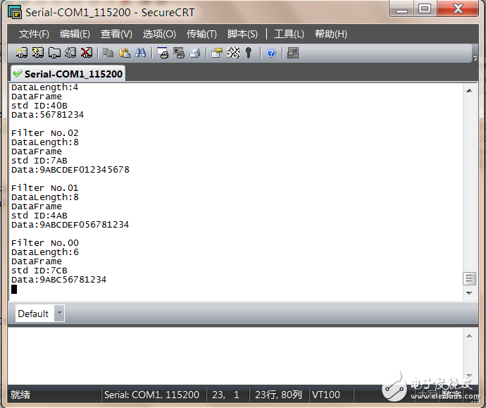
operation result:
Pharmaceuticals,2-Methyl- Propanoic Acid Monohydrate Price,2-Methyl- Propanoic Acid Monohydrate Free Sample,Pure 2-Methyl- Propanoic Acid Monohydrate
Zhejiang Wild Wind Pharmaceutical Co., Ltd. , https://www.wild-windchem.com