Abstract: With the continuous improvement of people's control requirements, capacitive touch screens are widely used because they can support multi-touch. This article is based on MeeGo, an open source operating system developed by Nokia and Intel, and uses a Linux input subsystem based on kernel objects to design the touch screen driver. This solution greatly facilitates the development of touch screen drivers and can be applied to electronic products such as car entertainment, netbooks, and smart phones.
introduction
With the continuous improvement of people's control requirements, more and more high-end mobile phones and tablet computers appear on the market. The common feature of these products is that they provide people with a very convenient control method, especially the use of capacitive touch screens. Realize multi-touch function well. Multi-touch technology is the hottest technology today, it has brought unprecedented changes in people's lifestyles. Capacitive touch screens have become the standard for high-end mobile phones, such as Apple ’s iPhone and some high-end mobile phones of HTC Motorola. Although the current price of capacitive screens is more expensive, as the technology improves, their prices will definitely drop, plus it will give users With the rich experience it brings, the use of capacitive touch screens is bound to become more and more widespread. MeeGo is an open source operating system jointly developed by Intel and Nokia. It is based on the Linux kernel, and its good open source provides a good basis for driver development. This design is under MeeGo 1.1 version, and based on Linux 2.6.35 kernel to discuss the driver development technology to realize capacitive touch screen.
1 Principle of capacitive touch screen
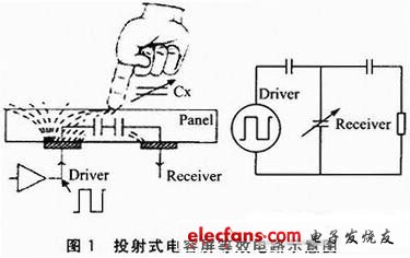
Capacitive touch screens use the current induction of the human body to work. They are divided into surface capacitive types and projected capacitive types. The former cannot recognize multiple points and the latter can recognize multiple points. Therefore, the projected capacitive touch screen is designed. The projected capacitive touch screen is a sensor that uses the touch screen electrodes to emit electrostatic field lines to work. It is divided into interactive capacitance and self capacitance. The design uses an interactive capacitive touch screen. It is made of ITO (indium tin oxide) on the glass surface to make horizontal and vertical electrodes. The intersection of the two groups of electrodes will form a capacitor, that is, these two groups of electrodes form the two poles of the capacitor.
When the capacitive screen is touched by the finger, the finger will absorb a small current, thereby changing the coupling between the electrodes near the touch point, which will change the capacitance between the two electrodes. When detecting the size of the projected capacitive screen, the horizontal electrodes sequentially emit signals, and all the vertical electrodes simultaneously receive signals, so that the capacitance value at the intersection of the two electrodes can be obtained, that is, the capacitance value of the entire touch screen plane. The coordinates of each touch point can be calculated accordingly. FIG. 1 is a schematic diagram of an equivalent circuit of a projected capacitive screen.

2 Linux input subsystem
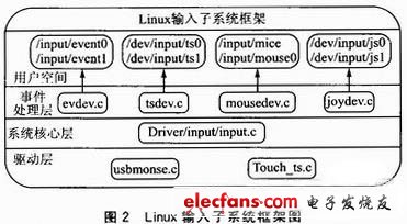
The Linux input subsystem (hereinafter referred to as the input subsystem) is implemented based on the kernel object kobject and is used in the Linux 2.6.35 kernel. With this mechanism, the kernel outputs various messages of the device to the user space through the input subsystem, which facilitates the management of the device. The input subsystem is composed of three parts: system core layer, driver layer and event processing layer. An input event such as mouse movement, keyboard key press and other operations reaches the user space through the driver layer, system core layer, and event processing layer, and is passed to the application program.
In this way, only the implementation of the driver layer needs to be considered when designing the driver, which reduces the workload and reduces the design difficulty. In addition, the design based on the subsystem improves the portability and adaptability of the driver, because the design of the driver based on the subsystem does not need to consider the interface of the input device reported to the upper layer. This work is completed by the input subsystem The subsystem is versatile to the interface of the upper layer, which can extend the use of the driver. Figure 2 is a framework diagram of the Linux input subsystem.

3 Touch screen driver design
3.1 Working principle of touch screen driver
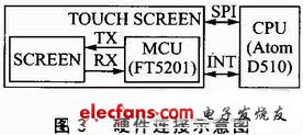
This design focuses on the overall design of the touch screen driver. This design process is also applicable to the design and development of other touch screen drivers. This design can use the SPI bus as the interface between the touch screen and the processor. The hardware connection diagram is shown in Figure 3. TOUCH SCREEN is a capacitive touch screen, which can use the FT5201 capacitive full-screen touch chip. INT is an interrupt pin. When the touch screen is touched, the interrupt handler is triggered by the INT pin. The CPU can use Intel's Atom D510 processor.

The SPI bus is a high-speed, full-duplex, synchronous communication bus. It works in a master-slave mode. There are four lines: SDI (data input), SDO (data output), CLK (clock), and CS (chip select ). In order to exchange data with peripherals, the SPI bus output phase and polarity of the serial synchronous clock can be configured according to the peripheral working requirements. The clock phase (CPHA) can be configured to select one of two different transmission protocols for data transmission. If CPHA = 0, data is sampled on the first transition edge (rising or falling) of the serial synchronous clock; if CPHA = 1, data is sampled on the second transition edge (rising or falling) of the serial synchronous clock sampling. The clock polarity (CPOL) has no significant impact on the transmission protocol. If CPOL = 0, the idle state of the serial synchronous clock is low; if CPOL = 1, the idle state of the serial synchronous clock is high.
SMC connectors
compact and reliable with high signal integrity
SMC connectors (Small Multiple Connector) have a grid of 1.27 millimeters and are available with pin counts of 12 to 80. Reliable and compact connections can be made with them. Various shapes, such as straight or angled male and female terminal strips, enable different mating configurations. The combination of different height male and female terminal strips results in diverse board-to-board spacing. The SMC connector also supports wire-to-board solutions.
comprehensive portfolio
reliable connections
robust and industry-capable
vibration and shock resistant
completely automatically processible
gold-plated contacts
dual beam female contacts
large operating temperature range
data rates up to 3 Gbit/s
high current rating
SMC connectors for many applications
The SMC connectors offer ideal solutions everywhere small grid and high performance are required. The outstanding signal integrity and a relatively high current rating include an enormous variety of application possibilities.
Since SMC connectors work reliably under adverse conditions and are very robust, they are especially suitable for instrumentation and industrial applications. Areas of application of these safe, outstandingly processed elements are factory and process automation, industrial robots, switches or PLC controls and modular control systems for communication between controller and I/O modules use.
Other application possibilities are:
medical technology
automotive
rail technology
electromobility
instrumentation
access and control systems
1.27mm Pitch BTB, SMC Connector,Small Multiple Connector, Board To Board Connector
ATKCONN ELECTRONICS CO., LTD , https://www.atkconn.com