Radar systems are becoming more complex and diverse, and system design, production, and maintenance are becoming more and more difficult. If the radar performance test uses real targets to provide radar test signals, the cost is higher. Radar system simulation combines modern simulation technology and radar technology, and uses software to establish a model that meets user needs, which has the advantages of flexibility and economy. Radar target simulation is an important part of radar system simulation. Using DSP / FPGA's high-speed computing performance, direct digital synthesis (DDS) technology and digital radio frequency storage ( DRFM ) technology, you can achieve real-time simulation of target echo signals in multiple complex ways such as phase encoding, linear frequency modulation, nonlinear frequency modulation , To detect radar tracking accuracy, angular accuracy and other indicators.
1 Function and system composition
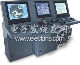
The multi-target radar simulator is designed to cooperate with a certain type of broadband radar system for equipment debugging and functional inspection. The simulator forms a simulated target echo by delaying, amplitude and phase modulation, and Doppler frequency shift of the radar transmission waveform, and sends it through the antenna or directly injects it into the test radar system. The target echo signal includes information such as the target's distance, angle, speed, radar scattering cross-sectional area (RCS), and one-dimensional range profile.
The overall system requirements are as follows: dual-channel output; frequency range from 5.2 to 5.8 GHz; narrowband instantaneous bandwidth of 10 MHz; wideband instantaneous bandwidth of 500 MHz; target number of 1-22; amplitude control range of 0-127 dB, quantization unit is not greater than 0.5 dB; RCS amplitude control rate is 1 μs, distance change amplitude control is 1 ms; target delay time: 2 ~ 4 000 μs; Doppler frequency shift range ± 400 kHz; phase noise is not greater than -90dBc / Hz @ 1 kHz; spur level is not greater than -55 dBc in narrow band; spur level is not greater than -45 dBc in wide band; distance simulation accuracy ≤1.5 m; Doppler simulation accuracy <1 Hz; input power It is -45 ~ + 30 dBm; the maximum output power is 20 dBm.
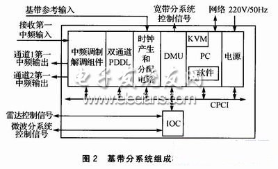
C-band radar target simulator consists of microwave subsystem, baseband subsystem, broadband subsystem, power control distribution components and software, as shown in Figure 1. The microwave subsystem includes a receiving component, a transmitting component, a frequency source component and a power supply. The baseband subsystem is mainly composed of the main control computer, digital management unit (DMU), interface control unit, dual-channel programmable digital delay line (PD-DL), clock generation and distribution circuit, intermediate frequency modulation and demodulation components and power supply. Narrowband target simulation is mainly realized by baseband subsystem and microwave subsystem.
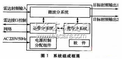
Broadband target simulation is mainly achieved by the baseband subsystem controlling the broadband subsystem, as shown in Figure 2. The output is output together with the narrow-band target signal through the microwave subsystem. The power control distribution component completes the functions of control, distribution, protection and indication of the main power supply of the system.
2 Target echo simulation
2.1 Narrowband target echo generation
The wideband radio frequency simulator receives the transmission signals, control signals and reference signals of the radar system. Before the system outputs the simulated narrow-band target echo signal, load the trajectory parameters of all targets and decoys, such as delay parameters and radial motion speed, and the amplitude / phase target characteristic files of each target and decoy on the main control computer.
After the simulation starts, the DMU controls the dual-channel PDDL and intermediate frequency modulation components in the narrow-band system to generate the baseband delay target signal according to the mode, parameters and trigger signals sent by the radar system. Modulation control, after filtering, forms a narrow-band target echo signal output, as shown in Figure 3.

2.2 Generation of broadband target echo
The generation of broadband target echo is achieved by directly calculating the baseband components and target characteristic parameters of the radar broadband LFM stored in memory in advance, and generating the waveform data of the multi-scattering point synthetic target in real time. As shown in Figure 4, all signals in the broadband sub-system are synchronized with the reference signal of the test radar system to ensure that the echo signal is coherent with the radar system to achieve correct simulation.

Before outputting the broadband target echo signal, load the trajectory parameter and target characteristic file of the output target scattering point on the computer. When the radar system transmits a broadband LFM signal, the baseband data of the broadband target echo is calculated by the DSP and loaded into the memory of the arbitrary waveform generator (AWG). The DMU generates the delayed trigger pulse and the waveform selection signal of the broadband subsystem, and controls the AwG to output the analog baseband echo signal. After quadrature modulation of the baseband signal, the target echo of the broadband signal is obtained by up-conversion. The target characteristic data is loaded into the DSP through the CompactPCI bus to participate in the waveform calculation.
The update rate of the broadband echo signal depends on the data update rate of the AWG. The principle of this digital method is simple, the simulation target is flexible, the accuracy is very high, and the signal quality is high. The disadvantage is that the cost is higher, and the real-time performance is limited by hardware speed and waveform complexity, and it is not easy to improve.

As shown in Figure 5, there are two TMS320C6455 high-performance DSPs, memory and large-scale FPGA in the DSP module, which complete the feature data reception, waveform calculation update and data transmission functions. It is the core control part of AWG. The FPGA of the AWG module uses XC4VLX25-FF668 from Xilinx. The DAC of the IQ signal path selects two Atmel's 1GHz 10-bit TS86101G2B, and the two DACs are independent of each other and keep the signal synchronized. Its single-channel instantaneous bandwidth can reach 400 MHz, and it can output complex modulation signals with the quadrature modulator.
WiFi 5 Outdoor Wireless AP is a wireless access point for outdoor environments. It is a device based on the IEEE 802.11ac standard, also known as WiFi 5. The device has a number of features and advantages that make it ideal for wireless networking in outdoor environments.
First, the WiFi 5 Outdoor Wireless AP has strong wireless signal coverage. It can provide longer transmission distances and wider coverage, enabling users to obtain a more stable and reliable wireless connection in outdoor environments. This is important for large outdoor Spaces such as campuses, parks, stadiums and city squares.
Second, WiFi 5 Outdoor Wireless AP has high wireless transmission speed. It supports multiple radio bands and multiple MIMO (multiple input multiple output) antenna technologies, which can provide higher data transfer rates. This means that users can enjoy wireless networking experiences such as faster web browsing, file downloads and video streaming in an outdoor environment.
In addition, the WiFi 5 Outdoor Wireless AP offers excellent network capacity and performance. It supports more simultaneous connected devices and can meet the needs of a large number of users to access the wireless network at the same time. This is important for busy outdoor venues such as music festivals, exhibitions and sporting events. In addition, it also supports QoS (Quality of Service) functions, which can prioritize applications and devices that require high network performance, providing a better user experience.
WiFi 5 Outdoor Wireless AP also has strong anti-interference capability. It uses advanced wireless technology and channel selection algorithms to automatically detect and avoid interference with other wireless devices. This makes it perform well in high-density wireless environments, such as city centers or business districts.
In addition, WiFi 5 Outdoor Wireless AP has good security. It supports security protocols such as WPA2-PSK (Wi-Fi Protected Access 2 Pre-Shared Key) and WPA3 (Wi-Fi Protected Access 3), which protect wireless networks from unauthorized access and data breaches. In addition, it supports features such as virtual private networks (VPNS) and firewalls to further enhance the security of the network.
The WiFi 5 Outdoor Wireless AP also has the advantage of being easy to install and manage. It usually has a user-friendly Web interface that makes it easy to set up and configure wireless networks. In addition, it supports a centralized management system that can manage and monitor multiple wireless access points from a central console, greatly simplifying network management.
Finally, WiFi 5 Outdoor Wireless aps typically have a durable design and protection against harsh outdoor environments. It is usually waterproof, dust-proof and earthquake-resistant, and can operate stably in various weather conditions. This makes it ideal for long-term use in outdoor places.
In summary, the WiFi 5 Outdoor Wireless AP is a device that provides stable, high-speed and secure wireless connectivity in outdoor environments. It has the characteristics and advantages of strong wireless signal coverage, high-speed wireless transmission speed, excellent network capacity and performance, strong anti-interference ability, good security, easy installation and management, and durable design and protection performance. This makes it ideal for deploying wireless networks in outdoor locations.
WiFi 5 Outdoor Wireless AP,WiFi 5 Outdoor Wireless AP oem,the best WiFi 5 Outdoor Wireless AP
Shenzhen MovingComm Technology Co., Ltd. , https://www.mcrouters.com